Hyundai Creta: Driveshaft Assembly / Dynamic Damper
Hyundai Creta GS 2014-2019 Service Manual / Driveshaft and axle / Driveshaft Assembly / Dynamic Damper
Components and components location
| Components |
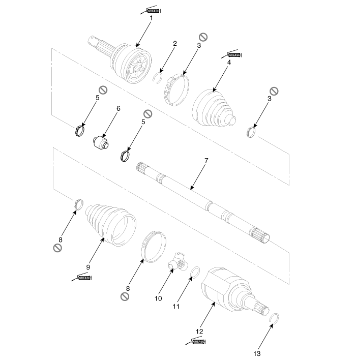
| 1. BJ
assembly 2. BJ circlip 3. BJ boot band 4. BJ boot |
5. Dynamic
damper band 6. Dynamic damper 7. Shaft 8. TJ boot band |
9. TJ
boot 10. Spider assembly 11. Retainer ring 12. TJ housing |
13. Housing
circlip |
Repair procedures
| Removal |
| 1. |
Remove the front driveshaft.
(Refer to Driveshaft Assembly - "Front Driveshaft")
|
| 2. |
Remove the TJ joint assembly.
(Refer to Driveshaft Assembly - "TJ Joint")
|
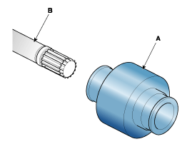
| 3. |
Remove the remove the both side of band (B) of the dynamic damper (A).
|

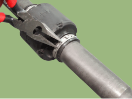
| 4. |
Fix the driveshaft (A) with a vice (B) as illustrated.
|

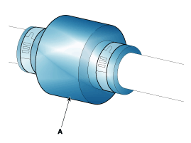
| 5. |
Apply soap powder on the shaft to prevent being damaged between the
shaft spline and the dynamic damper when the dynamic damper is removed.
|
| 6. |
Seperate the dynamic damper (A) from the shaft (B) carefully.
|
| Installation |
| 1. |
Apply soap powder on the shaft to prevent being damaged between the
shaft spline and the dynamic damper.
|
| 2. |
Install the dynamic damper.
|
| 3. |
Install the dynamic damper boot bands.
|
| 4. |
Install the TJ joint assembly.
(Refer to Driveshaft Assembly - "TJ joint")
|
| 5. |
Install the front driveshaft.
(Refer to Driveshaft Assembly - "Front Driveshaft")
|
| 6. |
Check the front alignment.
(Refer to Suspension System - "Alignment")
|
 TJ Joint
Components and components location
Components
[LH]
1. BJ assembly
2. BJ circlip
3. BJ boot band
4. BJ boot
5. Shaft
6. TJ boot ...
 BJ Boot
Components and components location
Components
1. BJ
assembly
2. BJ circlip
3. BJ boot band
4. BJ boot
5. Dynamic
damper band
6. Dynamic damper
...
Other information:
Hyundai Creta GS 2014-2019 Service Manual: Troubleshooting
Troubleshooting
Symptom
Suspected Area
Remedy
Abnormal noise
Oil level (Low)
To adding oil after inspect the parts (Oil seal, Drain plug, filler plug).
Oil (Wrong)
Replace t ...
Hyundai Creta GS 2014-2019 Service Manual: Temperature Control Actuator
Components and components location
Components Location
1. Temperature control actuator
Description and operation
Description
The temperature control actuator is located at the heater unit. It regulates
the temperature by the procedure ...
© 2017-2026 www.hcrmangs.com
