Hyundai Creta: Crash Pad / Main Crash Pad Assembly
Components and components location
| Component Location |
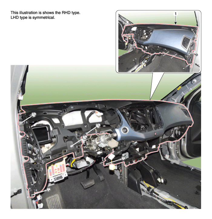
| 1. Main crash pad assembly |
Repair procedures
| Replacement |
|

|

| 1. |
Disconnect the negative (-) battery terminal.
|
| 2. |
Remove the front pillar trim.
(Refer to Interior Trim - "Front Pillar Trim")
|
| 3. |
Remove the cowl side trim.
(Refer to Interior Trim - "Cowl Side Trim")
|
| 4. |
Remove the audio unit.
(Refer to Body Electrical System - "Audio Unit")
|
| 5. |
Remove the crash pad lower panel.
(Refer to Crash Pad - "Crash Pad Lower Panel")
|
| 6. |
Remove the glove box housing.
(Refer to Crash Pad - "Glove Box Housing")
|
| 7. |
Remove the steering column shroud lower panel.
(Refer to Crash Pad - "Steering Column Shroud Panel")
|
| 8. |
Remove the steering wheel.
(Refer to Steering System - "Steering Wheel")
|
| 9. |
Remove the multifunction switch assembly.
(Refer to Body Electrical System - "Multifunction Switch")
|
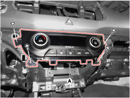
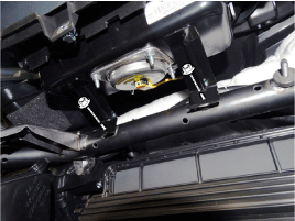
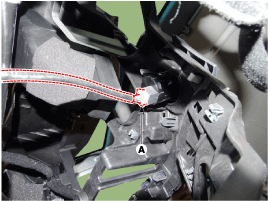
| 10. |
After loosening the mounting screws, then remove the heater & A/C controller
(A).
|
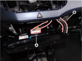
| 11. |
Disconnect the connectors (A) and hose (B).
|
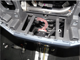
| 12. |
Disconnect the hazard switch connector (A).
|
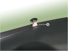
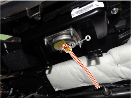
| 13. |
Disconnect the photo sensor connector (A).
|
| 14. |
Loosen the mounting nuts.
|
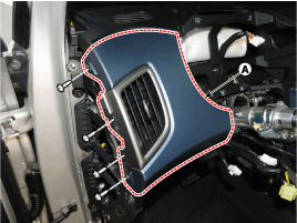
| 15. |
After loosening the mounting screws, then remove the crash pad garnish
[LH] (A).
|
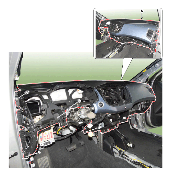
| 16. |
After loosening the mounting bolts and nuts, then remove the main crash
pad assembly (A).
|
| 17. |
Disconnect the start button connector (A).
|
| 18. |
Disconnect the passenger's airbag connectors (A).
|
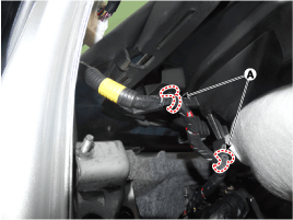
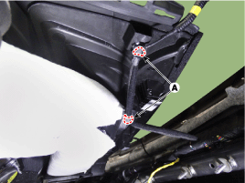
| 19. |
Right before removing the main crash pad, slightly lift the main crash
pad and remove the twitter speaker connector mounting clips (A) located
at the end of both side.
[LH]
[RH]
|
| 20. |
To install, reverse the removal procedure.
|
 Crash Pad Side Cover
Components and components location
Component Location
[LH]
1. Crash pad side cover [LH]
[RH]
1. Crash pad s ...
 Cowl Cross Bar Assembly
Components and components location
Component Location
1. Cowl cross bar assembly
Repair procedures
Replacement
...
Other information:
Hyundai Creta GS 2014-2019 Service Manual: Parking Brake Lever: Repair procedures
Removal
•
The parking brake cables must not be bent or distorted. This
will lead to stiff operation and premature failure.
1.
...
Hyundai Creta GS 2014-2019 Service Manual: Rear Door Belt Outside Weatherstrip: Repair procedures
Replacement
1.
Pull down rear door window glass by pressing the power window glass
switch.
2.
Remove the rear door belt outside weatherstrip (A).
3.
To install, reverse the removal procedure.
...
