Hyundai Creta: ESP(Electronic Stability Program) System / Schematic diagrams
Hyundai Creta GS 2014-2019 Service Manual / Brake System / ESP(Electronic Stability Program) System / Schematic diagrams
| Schematic diagram |
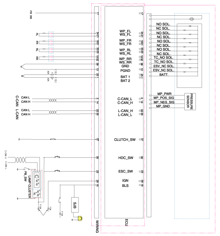
| Terminal Function |
ABS Connector Input/ Out put
|
Wire No. |
Designation |
Current12V(AMPS) |
max.permissible wire resistance (OHMS) |
|
13 |
Ground for recirculation pump |
137(Rush) |
10 m |
|
38 |
Ground for solenoid valves and ECU |
40 |
10m |
|
1 |
Voltage supply for pump motor |
137(Rush) |
10 m |
|
25 |
Voltage supply for solenoid valves |
40 |
10m |
|
29 |
IGNITION1(+) |
50m |
60m |
|
21,31,20,32 |
Active wheel signal wheel speed sensor FL, FR, RL,RR signal |
16.8m |
250m |
|
34,18,33,19 |
Voltage supply for the active wheel speed sensor FL,FR, RL, RR |
30m |
250 m |
|
16 |
Brake light switch (Signal) |
10m |
250m |
|
14 |
Chassis CAN High |
30m |
250 m |
|
17 |
Wheel speed sensor output |
16m |
250m |
|
2 |
Chassis CAN Low |
30m |
250 m |
|
23 |
ESP ON/OFF switch |
10m |
250 m |
|
30 |
HDC ON/OFF switch |
10m |
250 m |
|
22 |
Local CAN High |
30m |
250 m |
|
35 |
Local CAN Low |
30m |
250m |
|
35 |
Clutch switch |
10m |
250m |
 Description and operation
Description of ESP
Optimum driving safety now has a name : ESP, the Electronic Stability Program.
ESP recognizes critical driving conditions, such as panic reactions in dangero ...
 Troubleshooting
Failure Diagnosis
1.
In principle, ESP and TCS controls are prohibited in case of ABS failure.
2.
When ESP or TCS fails, only the failed sy ...
Other information:
Hyundai Creta GS 2014-2019 Service Manual: CVVT & Camshaft
Components and components location
Components
1. Exhaust camshaft
2. Intake camshaft
3. Exhaust CVVT
4. Intake CVVT
5. Camshaft bearing cap
6. Camshaft front bearing cap
7. O-ring
8. OCV (Oil Control Valve) adapter
Description and op ...
Hyundai Creta GS 2014-2019 Service Manual: Description and operation
Description
Communication Network Diagram
Abbreviation
Explanation
4WD_ECU
4WD Control Unit
A/CON
Aircon Control
ACU
Airbag Control Unit
B_CAN
...
© 2017-2026 www.hcrmangs.com
