Hyundai Creta: Automatic Transaxle System / Automatic Transaxle
Components and components location
| Components Location (1) |
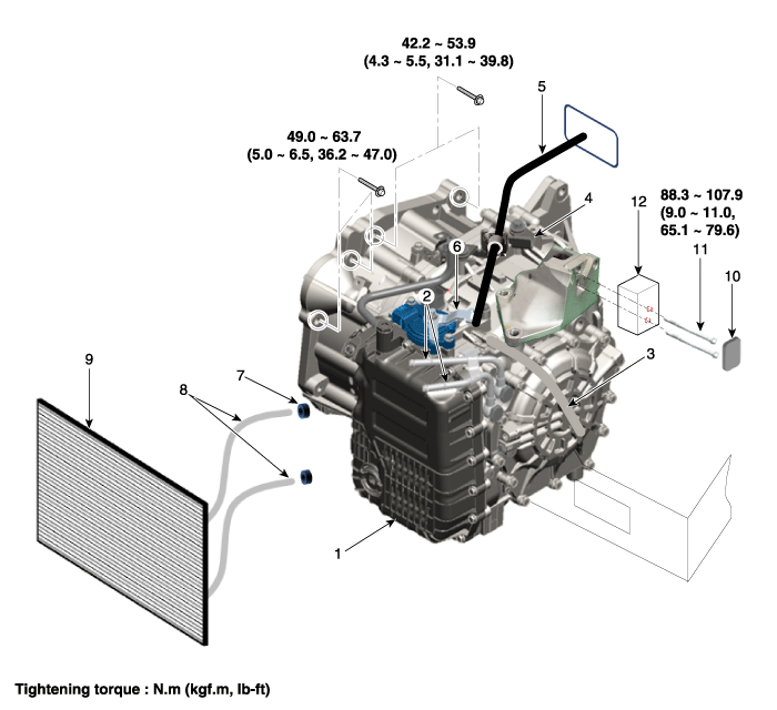
| 1. Automatic transaxle assembly 2. ATF cooler tube 3. Ground line 4. Shift cable mounting bracket 5. Shift cable 6. Inhibitor switch & manual control lever |
7. Clamp 8. ATF cooler hose 9. ATF Cooler & radiator 10. Mounting bracket cover 11. Support bracket mounting bolt 12. Automatic mounting bracket |
| Components Location (2) |
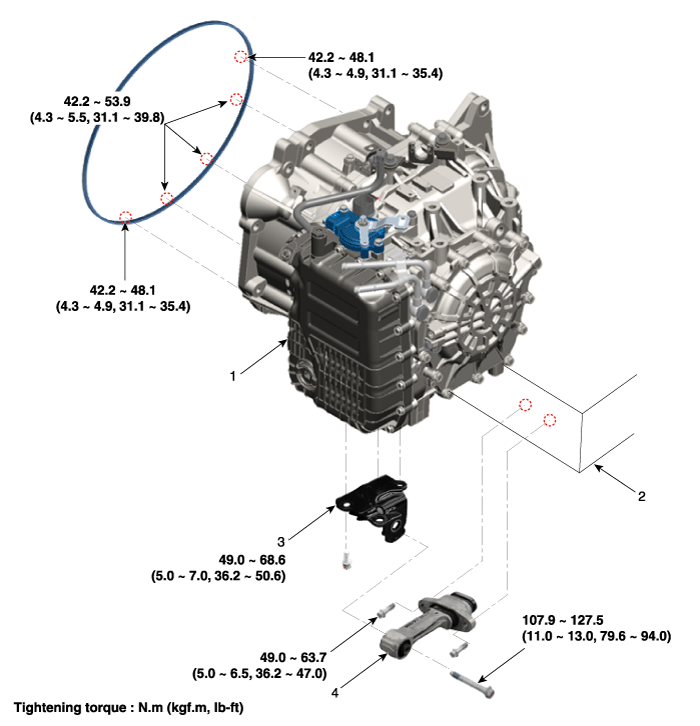
| 1. Automatic transaxle assembly 2. Subframe assembly |
3. Roll rod support bracket 4. Roll rod bracket |
Repair procedures
| Removal |
| 1. |
Remove the under cover.
(Refer to Engine Mechanical System - "Engine room under cover")
|
| 2. |
Remove the engine cover.
(Refer to Engine Mechanical System - "Engine cover")
|
| 3. |
Remove the air cleaner assembly and air duct.
(Refer to Engine Mechanical System - "Air cleaner")
|
| 4. |
Remove the battery and battery tray.
(Refer to Engine Electrical System - "Battery")
|
| 5. |
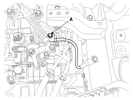
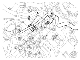
Remove the ground line after removing the bolt (A).
|
| 6. |
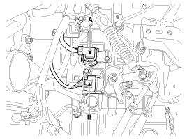
Dissconnect the solenoid valve connector (A) and inhibitor switch connector
(B).
|
| 7. |
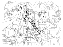
Remove the control cable (C) after removing the nut (A) and the bolt
(B).
|
| 8. |
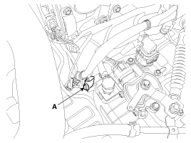
Remove the wiring mounting bolt (A) or clip.
|
| 9. |
Remove the solenoid valve connector and inhibitor switch connector wiring
mounting bracket (A) and (B).
|
| 10. |
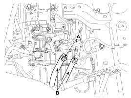
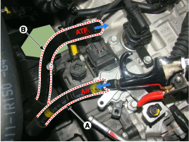
Disconnect the hose (B) after removing the automatic transaxle fluid
cooler hose clamp (A).
|
| 11. |
Remove the cowl top cover.
(Refer to Body - "Cowl Top Cover")
|
| 12. |
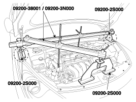
Assemble the engine support fixture(beam No.: 09200-38001 or 09200-3N000,
supporter No.: 09200-2S000).
(Refer to Special Service Tools - "Engine support fixture assembly drawing")
|
| 13. |
Using the engine support fixture assembly, hold the engine and transaxle
assembly safely.
|
| 14. |
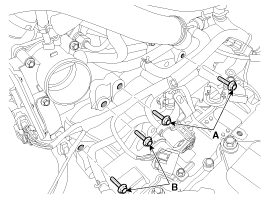
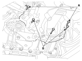
Remove the automatic transaxle upper mounting bolt (A-2ea) and the starter
motor mounting bolt (B-2ea).
|
| 15. |
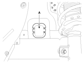
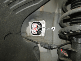
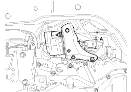
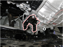
Remove the automatic transaxle mounting bracket cover (A).
|
| 16. |
Remove the automatic transaxle mounting bracket bolts (A).
|
| 17. |
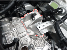
Remove the automatic transaxle mounting support bracket (A).
|
| 18. |
Lift the vehicle with a jack.
|
| 19. |
Remove the drive shaft assembly.
(Refer to Driveshaft and Axle - "Front Driveshaft")
|
| 20. |
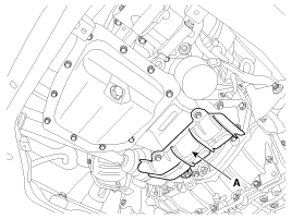
Remove the air guide (A).
|
| 21. |
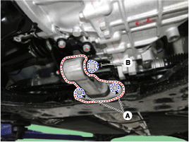
Remove the heater protector (A) after removing the bolt.
|
| 22. |
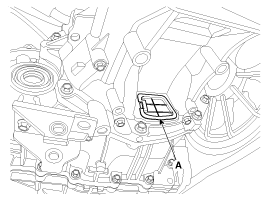
Remove the dust cover (A).
|
| 23. |
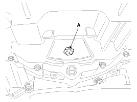
Remove the torque converter mounting bolts (A) with rotating the crankshaft
pulley.
|
| 24. |
Remove the roll rod bracket after removing the bolt (A) and (B).
|
| 25. |
Remove the roll rod support bracket (B).
|
| 26. |
Remove the automatic transaxle with a jack after removing the mounting
bolt (A-2ea, B-3ea).
|
| Installation |
| 1. |
To install, reverse the removal procedure.
|
| 2. |
In case of the reinstallation.
|
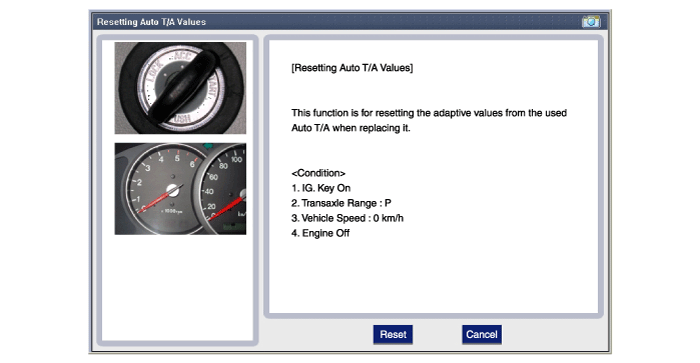
| 3. |
In case of the replacing with a new automatic transaxle.
|
Other information:
Lincoln Nautilus 2018-2026 Owners Manual: Keyless Entry – Troubleshooting
Keyless Entry – Frequently Asked Questions
Why does the keypad not accept the access code?
If you enter the access code too fast on
the keypad, the unlock function may not
work. Slowly re-enter the access code.
Why does the passive key not work?
The system deactivates passive keys
left inside y ...
Hyundai Creta GS 2014-2026 Service Manual: Rear Wheel Guard: Repair procedures
Replacement
•
Put on gloves to protect your hands.
•
When ...

