Hyundai Creta: Cooling System / Cooling Fan
Specifications
| Specifications |
|
Item |
Specification |
|
Fan type |
Puller |
|
Fan speed control |
Resistor (HI-LOW-OFF) |
|
Air flow rate [㎥/h (yd³/h)] |
1850 +8% MIN. |
|
Fan speed (rpm) |
2050 ±8% |
|
Current (A) |
13.3 +10% MAX. |
Components and components location
| Components |
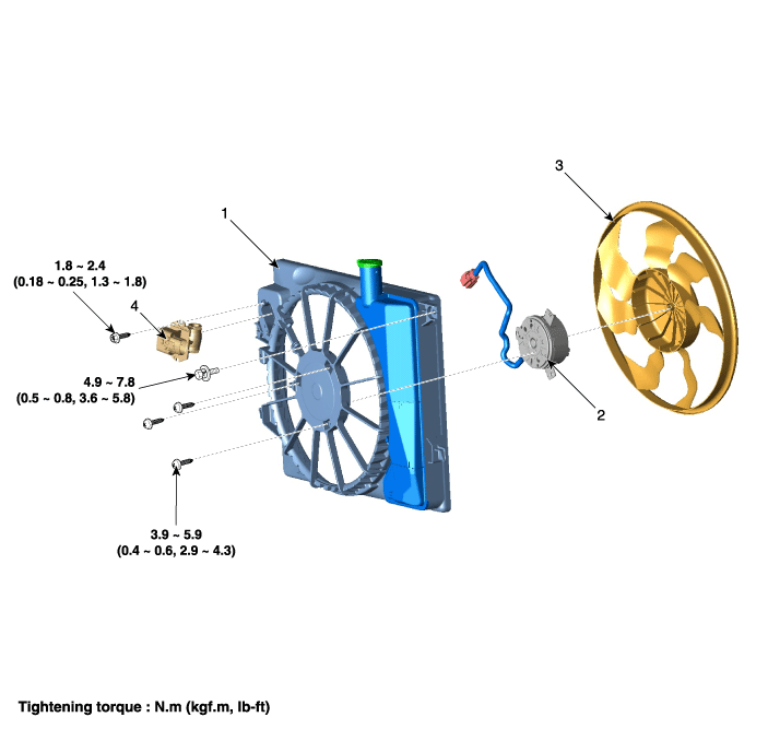
| 1. Cooling fan 2. Fan motor |
3. Cooling fan shroud 4. Cooling fan resistor |
Description and operation
| Description |
|
A/C switch |
A/C pressure [kgf/cm² G (psi G)] |
Vehicle speed [km/h (mph)] |
Coolant temperature [°C (°F)] |
Cooling fan speed |
|
OFF |
ă…ˇ |
V < 45 (28) |
95 ~ 100 (203 ~ 212) |
LOW |
|
100 (212) or above |
HIGH |
|||
|
45 (28) ≤ V < 80 (49.7) |
95 ~ 100 (203 ~ 212) |
LOW |
||
|
100 (212) or above |
HIGH |
|||
|
80 (49.7) ≤ V |
105 (221) or above |
HIGH |
||
|
ON |
P < 6 (85.3) |
All |
105 (221) or above |
HIGH |
|
6 (85.3) ≤ P < 12 (170.7) |
V < 45 (28) |
45 ~ 100 (113 ~ 212) |
LOW |
|
|
100 (212) or above |
HIGH |
|||
|
45 (28) ≤ V < 80 (49.7) |
95 ~ 100 (203 ~ 212) |
LOW |
||
|
100 (212) or above |
HIGH |
|||
|
80 (49.7) ≤ V |
105 (221) or above |
HIGH |
||
|
12 (170.7) ≤ P < 15.5 (120.5) |
V < 45 (28) |
-30 ~ 95 (-22 ~ 203) |
LOW |
|
|
95 (203) or above |
HIGH |
|||
|
45 (28) ≤ V < 80 (49.7) |
95 ~ 100 (203 ~ 212) |
LOW |
||
|
100 (212) or above |
HIGH |
|||
|
80 (49.7) ≤ V |
105 (221) or above |
HIGH |
||
|
15.5 (120.5) ≤ P |
All |
-30 (-22) or above |
HIGH |
|
A/C switch |
A/C pressure [kgf/cm² G (psi G)] |
Vehicle speed [km/h (mph)] |
Coolant temperature [°C (°F)] |
Cooling fan speed |
|
OFF |
ă…ˇ |
V < 45 (28) |
95 ~ 100 (203 ~ 212) or above |
HIGH |
|
45 (28) ≤ V < 80 (49.7) |
95 ~ 100 (203 ~ 212) or above |
HIGH |
||
|
80 (49.7) ≤ V |
105 (221) or above |
HIGH |
Schematic diagrams
| Circuit Diagram |
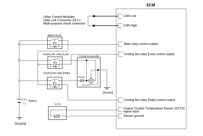
Repair procedures
| Removal and Installtion |
| 1. |
Disconnect the battery negative terminal.
|
| 2. |
Remove the air duct
(Refet to Intake And Exhaust System - " Air Cleaner")
|
| 3. |
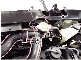
Separate the filler neck (A) from the radiator upper member assembly.
|
| 4. |
Disconnect the radiator reservoir hose (B).
|
| 5. |
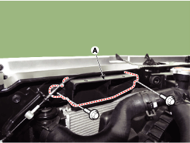
Disconnect the air duct(A).
|
| 6. |
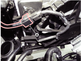
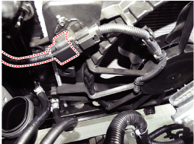
Disconnect the cooling fan connector (A).
|
| 7. |
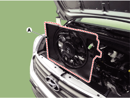
Remove the cooling fan (A) from the vehicle.
|
| 8. |
Install in the reverse order of removal.
|
| 1. |
Disconnect the wire harness connector (A) and the fan motor connector
(B).
|
| 2. |
Remove the resistor (A) from the cooling fan shroud.
|
| 3. |
Install in the reverse order of removal.
|
| Disassembly |
| 1. |
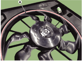
Remove the cooling fan (A) from the cooling fan assembly.
|
| 2. |
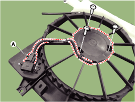
Disconnect the fan motor connector (A) from the resistor.
|
| 3. |
Remove the fan motor (B) from the cooling fan shroud.
|
| 4. |
Install in the reverse order of removal.
|
| Inspection |
| Fan Motor |
| 1. |
Disconnect the fan motor connector from the resistor.
|
| 2. |
Connect the battery voltage to the "+" terminal and ground to "-" terminal.
|
| 3. |
Check the cooling fan motor operates well.
|
 Coolant: Repair procedures
Replacement And Air Bleeding
•
Never remove the radiator cap when the engine is hot. ...
 Radiator
Components and components location
Components
1.
Radiator upper bracket (RH)
2. Radiator upper bracket (LH)
3. Mounting insulator
4. ...
Other information:
Lincoln Nautilus 2018-2025 Owners Manual: Massage Seats
Massage Seat Limitations
The engine must be running or the vehicle
must be in accessory mode to activate the
seats.
Allow a few seconds for any selection to
activate. When the seat backrest and cushion
are both active, the massage alternates
between zones.
Adjusting the Massage Seat Settings
...
Lincoln Nautilus 2018-2025 Owners Manual: Creating a Vehicle Wi-Fi Hotspot
You can create a Wi-Fi hotspot in your
vehicle and allow devices to connect to it for
access to the Internet.
Tap the vehicle drawer on the top left of the
screen.
Press Settings.
Press Vehicle Hotspot.Note: The vehicle hotspot default
setting is
on.
Press Settings under the Vehicle Hotspo ...

