Hyundai Creta: Brake System / Front Disc Brake
Components and components location
| Components |
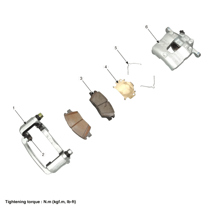
| 1. Caliper carrier 2. Pad retainer 3. Brake pad |
4. Inner pad shim 5. Pad return spring 6. Caliper body |
Repair procedures
| Removal |
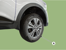
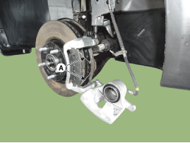
| 1. |
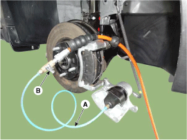
Remove the front wheel & tire (A).
|
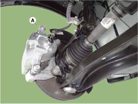
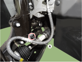
| 2. |
Disconnect the brake hose from the brake caliper by loosening the bolt
(A).
|
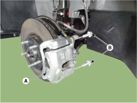
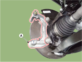
| 3. |
Loosen the guide rod bolt (B) and down the caliper carrier (A).
|
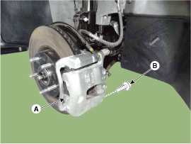
| 4. |
Loosen the brake hose mounting bolt (A).
|
| 5. |
Remove the pad return spring (A) and then separate the brake pad.
|

| 6. |
Loosen caliper mounting bolts, then remove the front caliper assembly
(A).
|
| Replacement |
Brake pad replacement
| 1. |
Remove the front wheel & tire.
|
| 2. |
Loosen the guide rod bolt (B) and down the caliper carrier (A).
|
| 3. |
Loosen the brake hose mounting bolt (A).
|
| 4. |
Repalce the pad return spring, brake pad, pad retainer and inner pad
shim with a new one.
|
| 5. |
Use a SST (09581-2T100) when installing the brake caliper assembly.
|
| 6. |
Up the caliper body(A) then tighten the guide rod bolt(B).
|
| 7. |
Install the brake hose mounting bracket.
|
| Inspection |
Front brake disc thickness check
| 1. |
Check the brake pads for wear and fade.
|
| 2. |
Check the brake disc for damage and cracks.
|
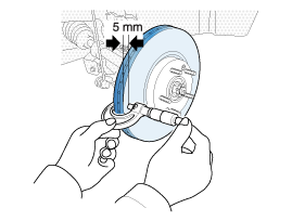
| 3. |
Remove all rust and contaminating materials from the surface, and measure
the disc thickness at the place of 5mm from the outer circumference
as the illustration below.
|
| 4. |
If wear exceeds the limit, replace the discs and pad assembly left and
right of the vehicle.
|
Front Brake Pad Check
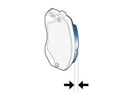
| 1. |
Check the pad wear. Measure the pad thickness and replace it, if it
is less than the specified value.
|
| 2. |
Check that grease is applied, to sliding contact points and the pad
and backing metal for damage.
|
Front brake disc runout check
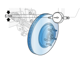
| 1. |
Place a dial gauge about 5mm (0.2 in.) from the outer circumference
of the brake disc, and measure the runout of the disc.
|
| 2. |
If the runout of the brake disc exceeds the limit specification, replace
the disc, and then measure the runout again.
|
| 3. |
If the runout does not exceed the limit specification, install the brake
disc after turning it 180° and then check the runout of the brake disc
again.
|
| 4. |
If the runout cannot be corrected by changing the position of the brake
disc, replace the brake disc.
|
| Installation |
| 1. |
Install in the reverse order of removal.
|
| 2. |
Use a SST (09581-2T100) when installing the brake caliper assembly.
|
| 3. |
After installation, bleed the brake system.
(Refer to Brake System - "Brake System Bleeding")
(Refer to Brake System - "ABS System Bleeding")
(Refer to Brake System - "ESPSystem Bleeding")
|
 Brake Pedal
Components and components location
Components
1.Stop lamp switch
2. Nut
3. Return spring
4. Brake pedal member assembly
5. Bolt
6. Brake pedal arm
...
 Rear Disc Brake
Components and components location
Components
1. Adjuster assembly
2. Upper return spring
3. Lever pawl
4. Shoe hold pin
5. Shoe hold spring
6. Shoe ho ...
Other information:
Hyundai Creta GS 2014-2019 Service Manual: Parking Assist Sensor
Components and components location
Component
Repair procedures
Removal
1.
Disconnect the negative (-) battery terminal.
2.
Remove the rear bumper cover.
(Refer to Body - "Rear Bumper Cover")
...
Hyundai Creta GS 2014-2019 Service Manual: Troubleshooting
Troubleshooting
Symptom
Suspect Area
Remedy (Refer to page)
Door glass fails to operate up and down
Incorrect window glass installation
Adjust position
Damaged or faulty regulator arm or reg ...
© 2017-2026 www.hcrmangs.com
