Hyundai Creta: Heater / Heater Unit
Components and components location
| Component Location |
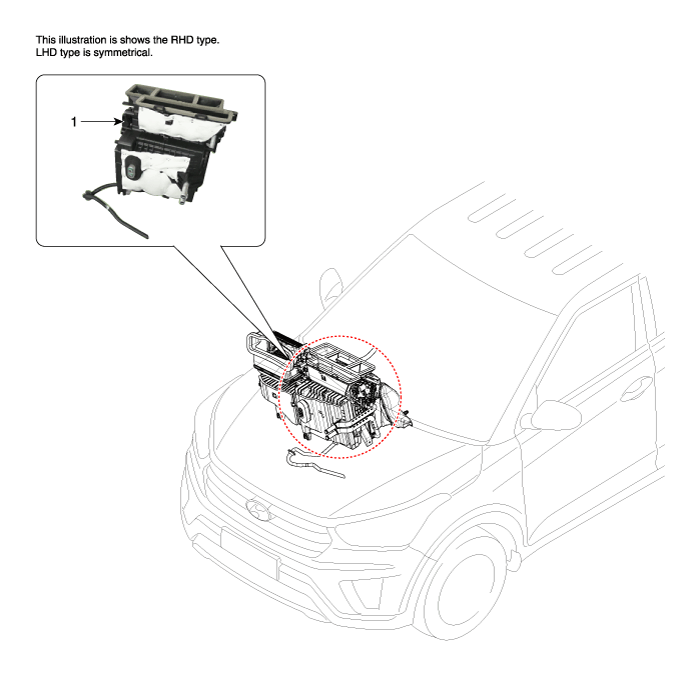
| 1. Heater unit assembly |
| Compoents (1) |
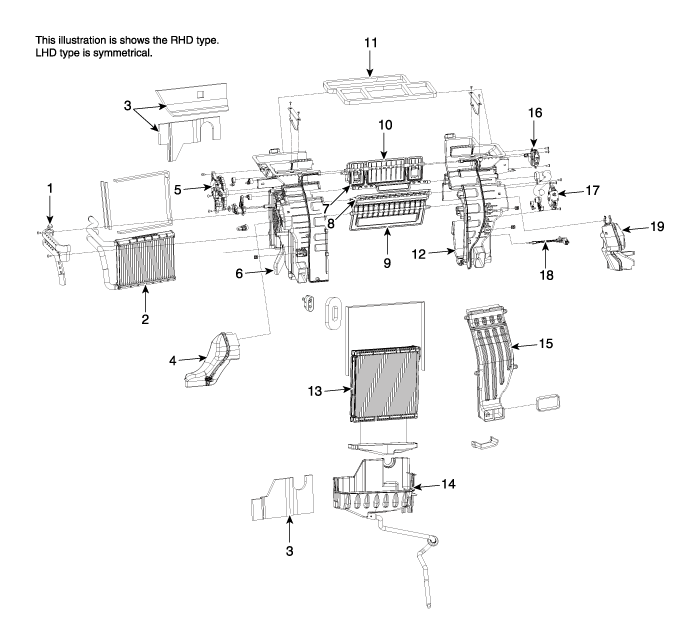
| 1. Heater core cover 2. Heater core & Seal assembly 3. Heater unit pad 4. Shower duct [LH] 5. Mode actuator 6. Heater case [LH] 7. Vent door assembly 8. Floor door assembly 9. Temperature door assembly 10. DEF door assembly |
11. Center duct seal 12. Heater case [RH] 13. Evaporator Core Assembly 14. Heater lower cover 15. Console duct cover 16. Auto defogging actuator 17. Temperature actuator motor assembly 18. Evaporator temperature sensor 19. Shower duct [RH] |
Repair procedures
| Replacement |
When prying with a flat-tip screwdriver or use a prying trim tool, wrap
it with protective tape, and apply protective tape around the related
parts, to prevent damage.
|
| 1. |
Disconnect the negative (-) battery terminal.
|
| 2. |
Recover the refrigerant with a recovery/recycling/charging station.
|
| 3. |
When the engine is cool, drain the engine coolant from the radiator.
(Refer to Engine Mechanical System - “Coolant”)
|
| 4. |
Remove the cowl top cover.
(Refer to Body - "Cowl Top Cover")
|
| 5. |
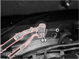
Remove the bolts and the expansion valve (A) from the evaporator core.
|
| 6. |
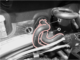
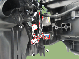
Disconnect the inlet (A) and outlet (B) heater hoses from the heater
unit.
|
| 7. |
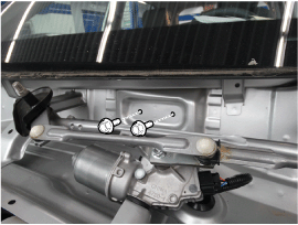
Loosen the cowl cross member mounting bolts.
|
| 8. |
Remove both sides of front seat assembly.
(Refer to Front Seat - "Front Seat Assembly")
|
| 9. |
Remove the main crash pad assembly.
(Refer to Crash Pad - "Main Crash Pad Assembly")
|
| 10. |
Disconnect the steering column connectors.
(Refer to Steering System - "Steering Column and Shaft")
|
| 11. |
Down the steering column after loosening the mounting bolts.
(Refer to Steering System - "Steering Column and Shaft")
|
| 12. |
Remove the shift lever assembly.
(Refer to Automatic Transaxle System - "Shift lever")
|
| 13. |
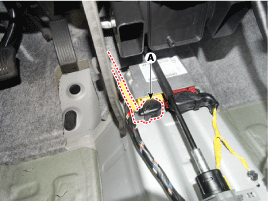
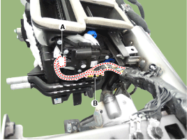
Disconnect the airbag control module (SRSCM) connector (A).
|
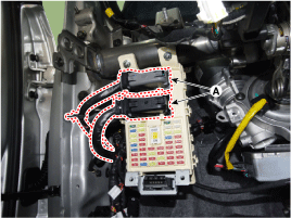
| 14. |
Disconnect the junction box connectors (A).
|
| 15. |
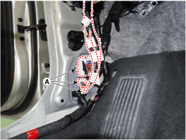
Disconnect the multi box connectors (A).
[Driver's side]
[Passenger's side]
|
| 16. |
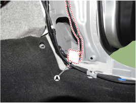
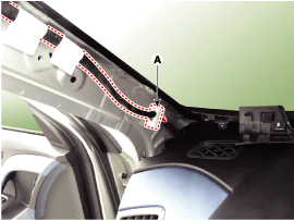
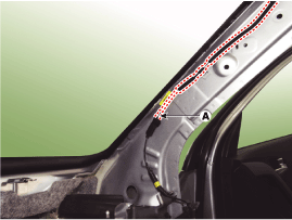
Disconnect the connectors (A) and the mounting clips in the front pillar.
[Driver's side]
[Passenger's side]
|
| 17. |
Separate the radiator assembly to obtain space for remove the air guard.
|
| 18. |
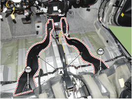
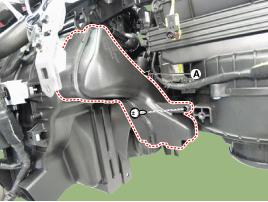
Remover the rear air duct (A) after detaching the nuts.
|
| 19. |
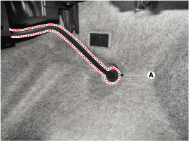
Remove the drain hose (A).
|
| 20. |
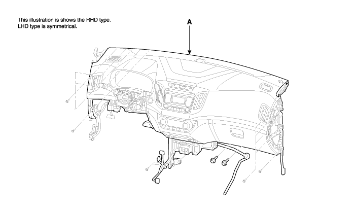
After loosening the bolts remove the main crash pad and cowl cross bar
assembly (A) together.
|
| 21. |
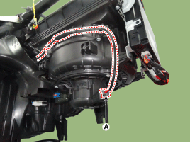
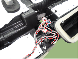
Disconnect the heater & blower unit connectors.
|
| 22. |
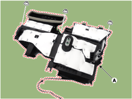
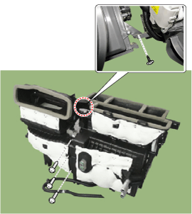
Remove the heater and blower unit (A) from the cowl cross bar after
loosening the mounting nuts.
|
| 23. |
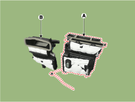
Separate the blower unit (B) from the heater unit (A) after loosening
the screws.
|
| 24. |
Install in the reverse order of removal.
|
 Heater
...
 Heater Core: Repair procedures
Replacement
1.
Disconnect the negative (-) battery terminal.
2.
Remove the heater and blower assembly.
(Refer to Heater -"Hea ...
Other information:
Lincoln Nautilus 2018-2026 Owners Manual: Tire Replacement Requirements
Your vehicle is equipped with tires
designed to provide a safe ride and
handling capability.
WARNING: Only use
replacement tires and wheels that are
the same size, load index, speed rating
and type (such as P-metric versus
LT-metric or all-season versus
all-terrain) as those originally provid ...
Hyundai Creta GS 2014-2026 Owners Manual: Operating door locks from outside
the vehicle
Mechanical key
Turn the key toward the rear of the
vehicle to unlock and toward the front
of the vehicle to lock.
If you lock/unlock the driver's door
with a key, all vehicle doors will
lock/unlock automatically. (if equipped
with the central door lock system)
Once the doors are u ...


