Hyundai Creta: Indicators And Gauges / Instrument Cluster
Components and components location
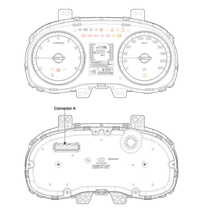
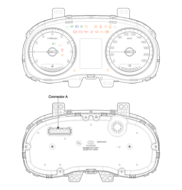
| Components |
| [Standard] |
| [Supervision] |
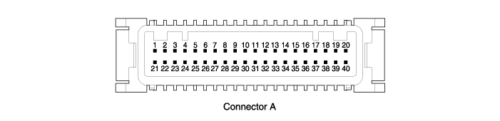
|
No |
Description |
No |
Description |
|
1 |
GND |
21 |
Trip switch (-)_input |
|
2 |
Illumination (-)_output |
22 |
Trip switch1 (+)_input |
|
3 |
Rheostat down switch |
23 |
- |
|
4 |
Rheostat up switch |
24 |
AT (P) output |
|
5 |
Alternator_input |
25 |
AT (R) output |
|
6 |
- |
26 |
AT (N) output |
|
7 |
- |
27 |
AT (D) output |
|
8 |
Oil Pressure switch_input |
28 |
AT (S) output |
|
9 |
Speed_output |
29 |
B_CAN (Low) |
|
10 |
- |
30 |
B_CAN (High) |
|
11 |
Alternator_output |
31 |
- |
|
12 |
Vehicle speed_input |
32 |
C_CAN (High) |
|
13 |
Air Bag (+)_input |
33 |
C_CAN (Low) |
|
14 |
Fuelsender (+)_input |
34 |
- |
|
15 |
Water seperator (+)_input |
35 |
Detent_ouput |
|
16 |
Fuelsender (-)_input |
36 |
- |
|
17 |
- |
37 |
GND_signal |
|
18 |
- |
38 |
- |
|
19 |
- |
39 |
IGN 1 |
|
20 |
Tail lamp_input |
40 |
Battery (+) |
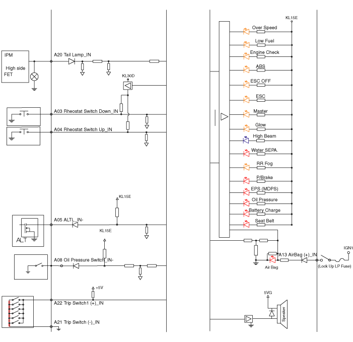
Schematic diagrams
| Circuit Diagram |
| [Standard] |
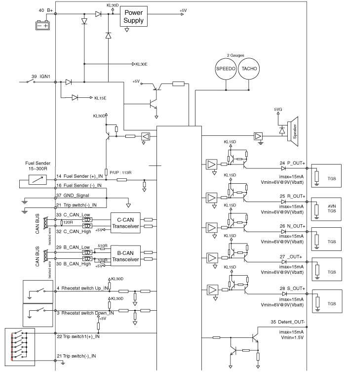
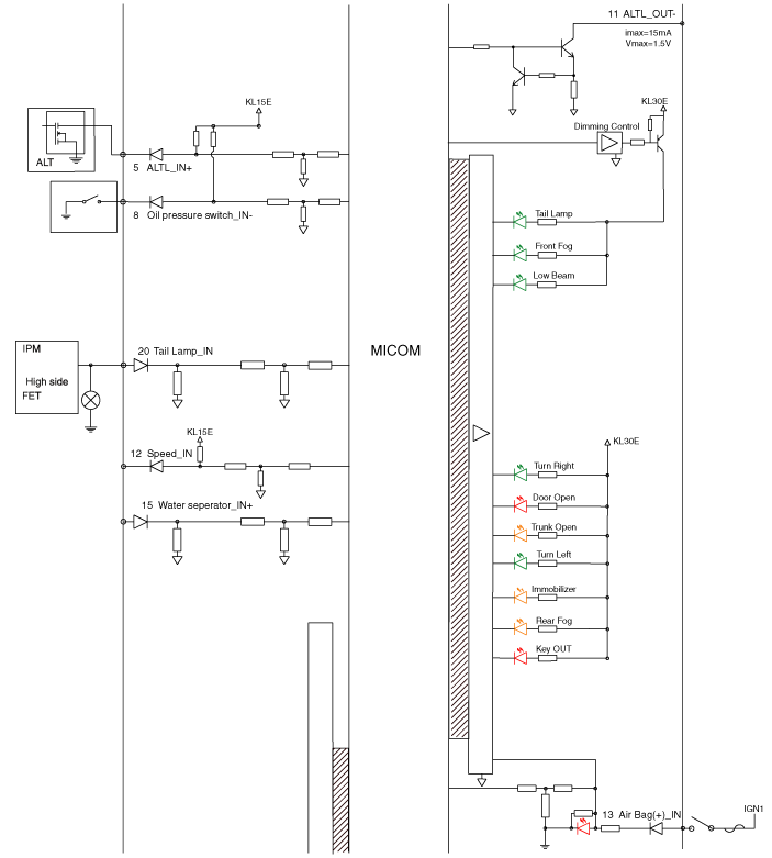
| [Supervision] |
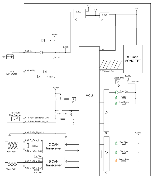
Description and operation
| Description |
|
Abbreviation |
Explanation |
|
4WD_ECU |
4WD Control Unit |
|
A/CON |
Aircon Control |
|
ACU |
Airbag Control Unit |
|
B_CAN |
Body Controller Area Network |
|
BCM |
Body Control Module |
|
C_CAN |
Chassis Controller Area Network |
|
CLU |
Cluster Module |
|
ECU |
Engine Control Unit |
|
MDPS |
Motor Driven Power Steering |
|
SAS |
Steering Angle Sensor |
|
SJB |
Smart Junction Block |
|
SMK |
Smart Key Unit |
|
TMU |
Telematics Unit |
|
RR_CAM |
Rear View Camera |
Repair procedures
| Removal |
| 1. |
Disconnect the negative (-) battery terminal.
|
| 2. |
Remove the cluster fascia panel.
(Refer to Body - "Cluster Fascia Panel")
|
| 3. |
Remove the cluster (A) from the housing after removing 4 screws.
|
| 4. |
Disconnect the cluster connecter (A) and then remove the cluster (B).
|
| Installation |
| 1. |
Connect the cluster connector.
|
| 2. |
Install the cluster assembly.
|
| 3. |
Install the cluster facia panel.
|
| 4. |
Connect the negative (-) battery terminal.
|
| Inspection |
| 1. |
Check point (Warning indicator)
|


| 2. |
Check the gauge functionality refer to below information when gauge
has a problem
|
| 1. |
The body electrical system can be quickly diagnosed failed parts with
vehicle diagnostic system (GDS)
The diagnostic system (GDS) provides the following information.
|
| 2. |
Select the "Car Model" and the system to be checked in order to check
the vehicle with the tester.
|
| 3. |
Select the "Body Control Module (BCM)" to check the "Cluster Module
(CLU)".
|
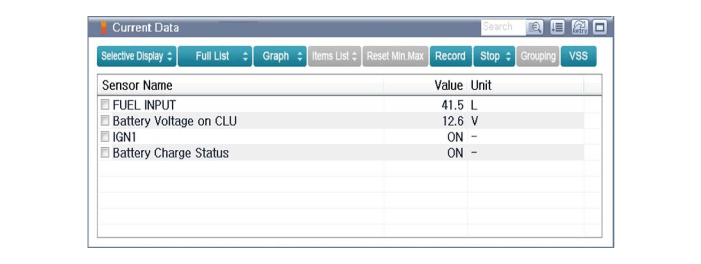
| 4. |
Select the "Current Data" menu to search the current state of the input/output
data.
The input/output data for the sensors corresponding to the cluster module
(CLU) can be checked.
|
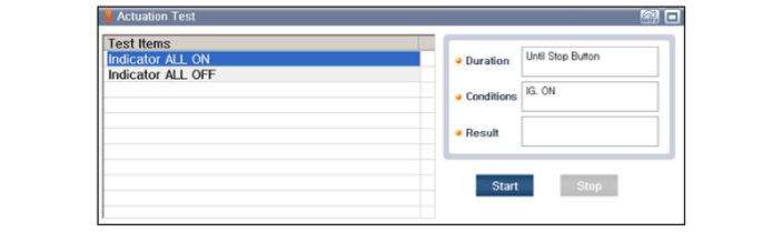
| 5. |
To check the input value of cluster illumination, select option "Actuation
Test".
|
| 1. |
Connect the cable of GDS to the data link connector in driver side crash
pad lower panel, turn the power on GDS.
|
| 2. |
Select the "Body Control Module (BCM)" to check the"'Cluster Module
(CLU)".
|
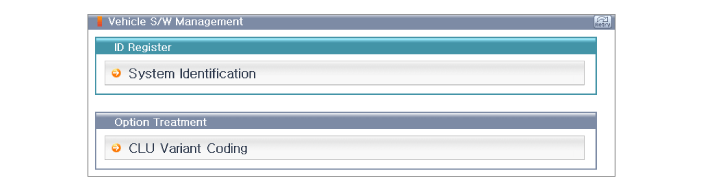
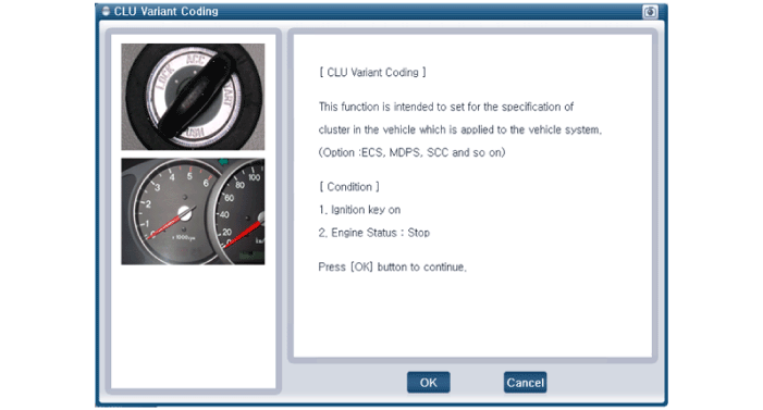
| 3. |
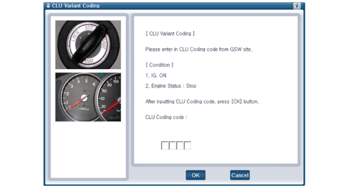
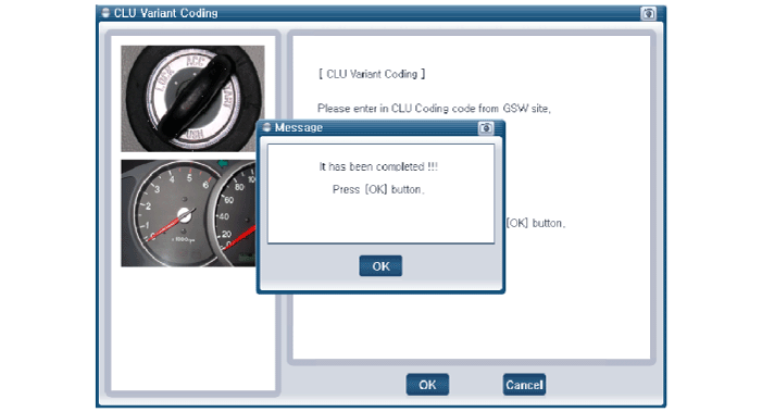
Select variant coding mode to perform.
|

 Power Door Locks
...
Other information:
Hyundai Creta GS 2014-2019 Service Manual: Inside Rear View Mirror
Components and components location
Component Location
1. Inside rear view mirror
Repair procedures
Replacement
[Manual Mirror]
•
...
Hyundai Creta GS 2014-2019 Service Manual: Special service tools
Special Service Tools
Tool(Number and Name)
Illustration
Use
Deployment tool
0957A-34100A
Airbag deployment tool.
Use with (0957A-AL120 and 0957A-AL150)
Dummy
0957A-38200
...
