Hyundai Creta: Manual Transaxle System / Manual Transaxle
Components and components location
| Components |
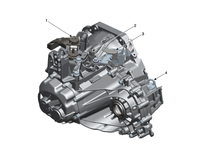
| 1. Control shaft complete 2. Back-up lamp switch |
3. Control cable bracket 4. Plug |
Repair procedures
| Removal |
| 1. |
Remove the air cleaner assembly.
(Refer to Engine Mechanical System - " Air Cleaner)
|
| 2. |
Remove the battery and battery tray.
(Refer to Engine Electrical System - "Battery")
|
| 3. |
Remove the ECM.
(Refer to Engine Control System - "ECM")
|
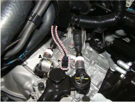
| 4. |
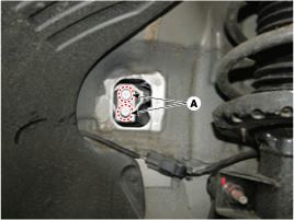
Disconnect the back-up lamp switch connector (A).
|
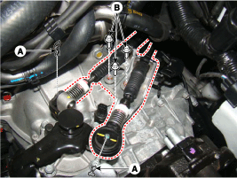
| 5. |
Disconnect the select or shift cable assembly after removing the pin
(A).
|
| 6. |
Remove the control cable bracket after removing the bolt (B-3ea).
|
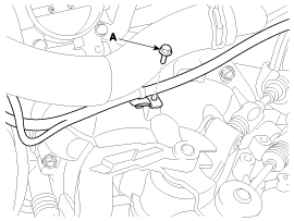
| 7. |
Remove the wiring bracket bolt (A).
|
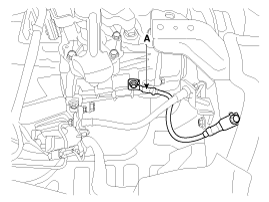
| 8. |
Remove the gruing cable from transaxle (A).
|
| 9. |
Remove the clutch tube bracket bolt (A).
|
| 10. |
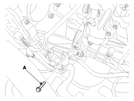
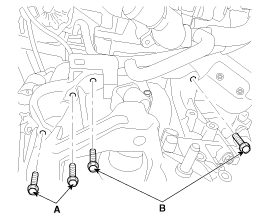
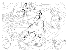
Remove the transaxle upper mounting bolt (B-2ea) and the start motor
mounting bolt (A-2ea).
|
| 11. |
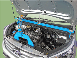
Assembled the engine support fixture. (beam No.: 09200-38001 or 09200-3N000,
supporter No.: 09200-2S000)
(Refer to Special Service Tools - " Engine support fixture special tool
assembly drawing")
|
| 12. |
Using the engine support fixture (A), hold the engine and transaxle
assembly safely.
|
| 13. |
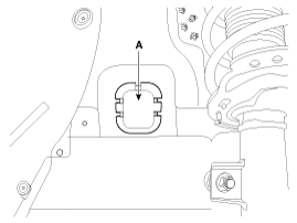
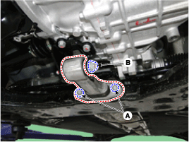
Remove the manual transaxle mounting bracket cover (A).
|
| 14. |
Remove the manual transaxle mounting bracket bolts (A).
|
| 15. |
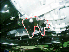
Remove the transaxle support mounting bracket (A).
|
| 16. |
Remove the under cover.
(Refer Engine Mechanical System - "Engine Room Under Cover")
|
| 17. |
Remove the drive shaft assembly.
(Refer to Drive shaft and axle - "Front Driveshaft")
|
| 18. |
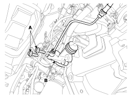
Remove the clutch release cylinder (B) after removing the bolt (A-2ea).
|
| 19. |
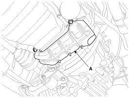
Remove the air guide bracket (A).
|
| 20. |
Remove the roll stopper after removing the bolt (A) and (B).
|
| 21. |
Remove the roll rod support bracket (B).
|
| 22. |
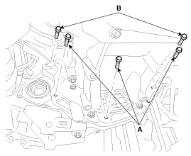
Remove the mounting bolts (A-4ea, B-2ea) of lower part of the transaxle,
and the left side cover and remove the transaxle assembly by supporting
it with a jack.
|
| Installation |
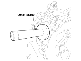
If the oil seal on the transaxle case side is damaged and fluid is leaking,
replace the oil seal with a new unit.
When installing the new oil seal, use the specialized tool (oil seal
installer, 09431-26100).
|
| 1. |
Add Manual transaxle fluid.
(Refer to Manual Transaxle System - "Manual Transaxle Fulid")
|
 Manual Transaxle Fluid
General information
General Information
1.
Check & Change intervals
Check
& Replenishment
Change
...
 Back-up Lamp Switch
Description and operation
Description
Component location : Manual transaxle case
Operation principle : Back up lamp switch is pushed by the reverse lug sliding
when select ...
Other information:
Hyundai Creta GS 2014-2019 Service Manual: Climate Control Air Filter
Description and operation
Description
The climate control air filter is located in the blower unit. It eliminates
foreign materials and odor. The particle filter performs a role as an odor filter
as well as a conventional dust filter to ensure comfortable interior environment ...
Hyundai Creta GS 2014-2019 Owners Manual: Recommended SAE viscosity
number
CAUTION
Always be sure to clean the area
around any filler plug, drain plug,
or dipstick before checking or
draining any lubricant. This is
especially important in dusty or
sandy areas and when the vehicle
is used on unpaved roads.
Cleaning the plug and dipstick
areas will prevent d ...

