Hyundai Creta: Power Door Locks / Power Door Lock Actuators: Repair procedures
Hyundai Creta GS 2014-2019 Service Manual / Body Electrical System / Power Door Locks / Power Door Lock Actuators: Repair procedures
| Inspection |
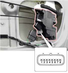
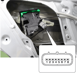
Front Door Lock Module Inspection
| 1. |
Remove the front door trim.
(Refer to Body - "Front Door Trim")
|
| 2. |
Remove the front door module.
(Refer to Body - "Front Door Module")
|
| 3. |
Disconnect the connectors from the actuator.
|
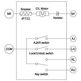
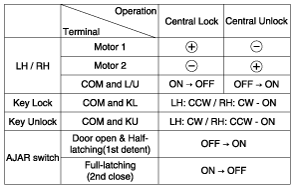
|||||||||||||||||||||||||||||
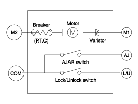
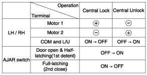
| 4. |
Check actuator operation by connecting power and ground according to
the table. To prevent damage to the actuator, apply battery voltage
only momentarily.
|
Rear Door Latch Inspection
| 1. |
Remove the rear door trim.
(Refer to Body - "Rear Door Trim")
|
| 2. |
Remove the rear latch.
(Refer to Body - "Rear Door Latch")
|
| 3. |
Disconnect the connectors from the actuator.
|
| 4. |
Check actuator operation by connecting power and ground according to
the table. To prevent damage to the actuator, apply battery voltage
only momentarily.
|
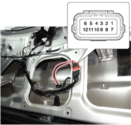
Tailgate Lock Module Inspection
| 1. |
Remove the tailgate trim.
(Refer to Body - "Tailgate Trim")
|
| 2. |
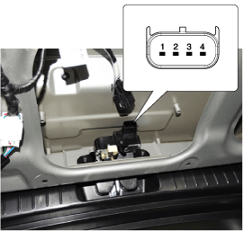
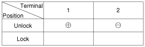
Disconnect the 4P connector from the actuator.
|
| 3. |
Check actuator operation by connecting power and ground according to
the table. To prevent damage to the actuator, apply battery voltage
only momentarily.
|
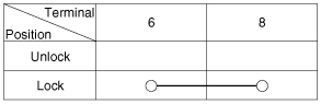
Tailgate Open Switch
| 1. |
Remove the tailgate trim.
(Refer to Body - "Tailgate Trim")
|
| 2. |
Disconnect the switch connector.
|
| 3. |
Check for continuity between the terminals in each switch position according
to the table.
|
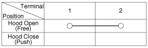
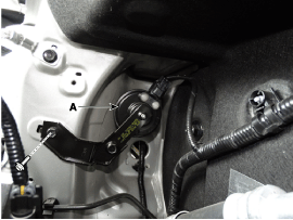
Hood Switch
| 1. |
Disconnect the connector (A) and bolts from the hood switch.
|
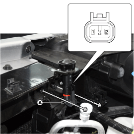
| 2. |
Check for continuity between the terminals and ground according to the
table.
|
Burglar Horn
| 1. |
Remove the burglar horn (A) after removing a bolt and disconnect the
2P connector from the burglar horn.
|
| 2. |
Test the burglar horn by connecting battery power to the terminal 1
and ground the terminal 2.
|
| 3. |
The burglar horn should sound. If the burglar horn fails to sound replace
it.
|
 Components and components location
Component Location
1. Driver power window main switch
2. Body Control Module (BCM)
3. Door look switch
4. Tailgate lock actuator & switch
5. Front door ...
 Power Door Lock Switch: Repair procedures
Diagnosis with GDS
1.
The BCM can be diagnosed by using the GDS. The BCM communicates with
the GDS which then displays inputs and outputs along with codes.
...
Other information:
Hyundai Creta GS 2014-2019 Service Manual: Flywheel: Repair procedures
Removal and installation
1.
Remove the manual transaxle.
(Refer to Manual Transaxle System - "Manual Transaxle")
2.
Remove the flywheel (A).
Tightening torque :
71.6 ~ 75.5 N.m (7.3 ...
Hyundai Creta GS 2014-2019 Service Manual: Fog Lamps: Repair procedures
Removal
1.
Disconnect the negative (-) battery terminal.
2.
Remove the front bumper.
(Refer to Body - "Front Bumper Cover")
3.
Remove the front fog lamp assembly (A) after loosening the mounti ...
© 2017-2026 www.hcrmangs.com
