Hyundai Creta: ABS(Anti-Lock Brake System) / Repair procedures
| Repair procedures |
| 1. |
Remove the reservoir cap and fill the brake reservoir with brake fluid.
|
| 2. |
Connect a clear plastic tube to the wheel cylinder bleeder plug and
insert the other end of the tube into a half filled clear plastic bottle.
|
| 3. |
Connect the GDS to the data link connector located underneath the dash
panel.
|
| 4. |
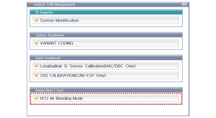
Select and operate according to the instructions on the GDS screen.
|
| 5. |
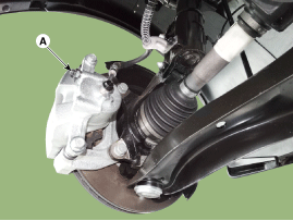
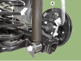
Pump the brake pedal several times, and then loosen the bleeder screw
until fluid starts to run out without bubbles. Then close the bleeder
screw (A).
[Front]
[Rear]
|
| 6. |
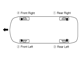
Repeat step 5 until there are no more bubbles in the fluid for each
wheel.
|
| 7. |
Tighten the bleeder screw.
|
 Troubleshooting
Standard Flow of Diagnostic Troubleshooting
Notes With Regard To Diagnosis
The phenomena listed in the following table are not abnormal.
Condition
Explanati ...
 ABS Control Module
Components and components location
Components
[LHD]
1. Front - RH
2. Rear - LH
3. Rear - RH
4. Front - LH
5. MC2
6. MC1
7. ABS control ...
Other information:
Hyundai Creta GS 2014-2026 Owners Manual: Owner maintenance precautions
Improper or incomplete service may
result in problems. This chapter gives
instructions only for the maintenance
items that are easy to perform.
Information
Improper owner maintenance during
the warranty period may affect warranty
coverage. For details, read the
separate Service Passpor ...
Lincoln Nautilus 2018-2026 Owners Manual: Wipers and Washers – Troubleshooting
Wipers and Washers – Warning Lamps
Illuminates when the windshield
washer fluid is low.
Wipers and Washers – Frequently Asked Questions
Why are there streaks and smears on the
windshield?
The wiper blades could be dirty, worn
or damaged. Check the wiper blades.
See Checking the Wiper Blades ...


