Hyundai Creta: ABS(Anti-Lock Brake System) / Schematic diagrams
Hyundai Creta GS 2014-2019 Service Manual / Brake System / ABS(Anti-Lock Brake System) / Schematic diagrams
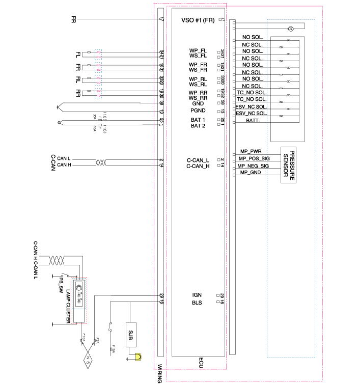
| Schematic diagram |

| Terminal Function |

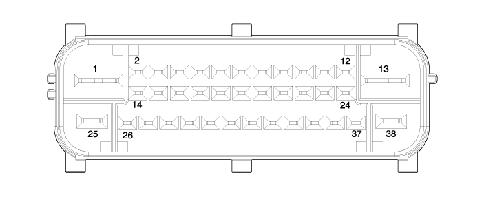
ABS Connector Input/ Out put
|
Wire No. |
Designation |
Current12V(AMPS) |
max.permissible wire resistance (OHMS) |
|
13 |
Ground for recirculation pump |
137(Rush) |
10 m |
|
38 |
Ground for solenoid valves and ECU |
40 |
10m |
|
1 |
Voltage supply for pump motor |
137(Rush) |
10 m |
|
25 |
Voltage supply for solenoid valves |
40 |
10m |
|
29 |
IGNITION1(+) |
50m |
60 m |
|
21,31,20,32 |
Active wheel signal wheel speed sensor FL, FR, RL,RR signal |
16.8m |
250m |
|
34,18,33,19 |
Voltage supply for the active wheel speed sensor FL,FR, RL, RR |
30m |
250 m |
|
16 |
Brake light switch (Signal) |
10m |
250m |
|
14 |
Chassis CAN High |
30m |
250 m |
|
17 |
Wheel speed sensor output |
16m |
250m |
|
2 |
Chassis CAN Low |
30m |
250 m |
|
7 |
G-sensor power |
50m |
250 m |
|
8 |
G-sensor ground |
50m |
250 m |
|
30 |
G-sensor signal |
50m |
250 m |
 Description and operation
Description
This specification applies to HCU(Hydraulic Control Unit) and ECU(Electronic
Control Unit) of the HECU.(Hydraulic and Electronic Control Unit)
This specification is ...
 Troubleshooting
Standard Flow of Diagnostic Troubleshooting
Notes With Regard To Diagnosis
The phenomena listed in the following table are not abnormal.
Condition
Explanati ...
Other information:
Hyundai Creta GS 2014-2019 Service Manual: Specifications
Specifications
Item
Specification
Type
Electric Power Steering System
Steering gear
Type
Rack & Pinion
Rack stroke
148 mm (5.83 in.) ± 1 (0.3937 in.)
...
Hyundai Creta GS 2014-2019 Service Manual: Rear Door Belt Outside Weatherstrip: Repair procedures
Replacement
1.
Pull down rear door window glass by pressing the power window glass
switch.
2.
Remove the rear door belt outside weatherstrip (A).
3.
To install, reverse the removal procedure.
...
© 2017-2026 www.hcrmangs.com

