Hyundai Creta: Automatic Transaxle Control System / Shift Lever
Components and components location
| Components Location |
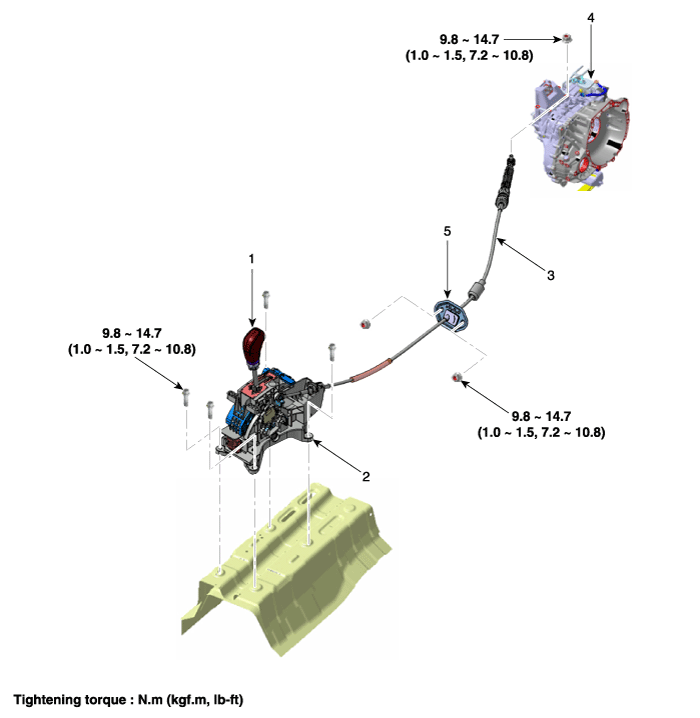
| 1. Shift lever knob & boots 2. Shift lever assembly 3. Shift cable |
4. Manual control lever 5. Shift cable retainer |
| Components |
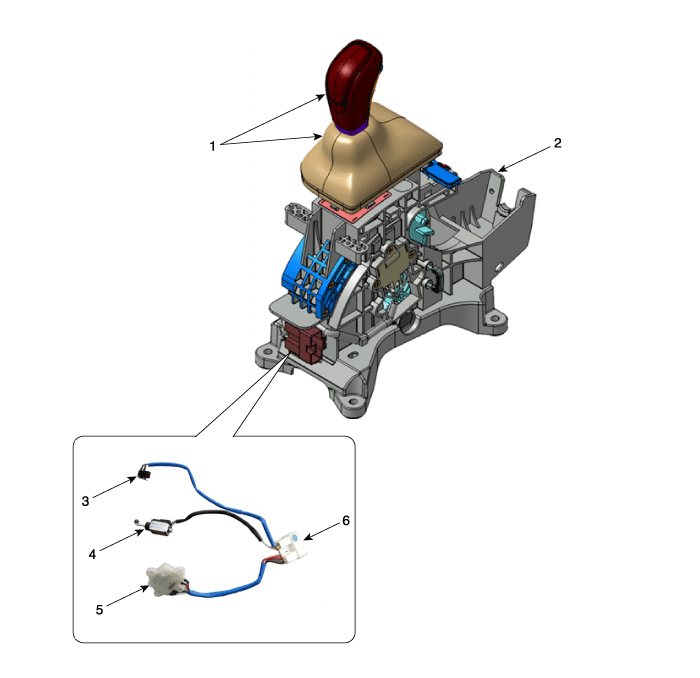
| 1. Shift lever & boots assembly 2. Shift lever assembly 3. P position switch |
4. Shift lock solenoid 5. Manual mode switch housing 6. Main connector |
Schematic diagrams
| Schematic Diagrams |
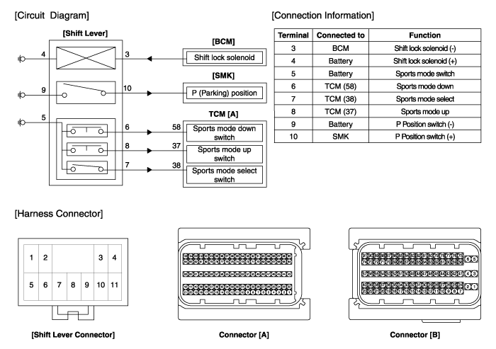
Repair procedures
| Removal |
| [RHD] |
| 1. |
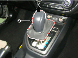
Disconnect a boots from the console upper cover.
|
| 2. |
Pull the knob (A) in the direction of "F" and remove the knob.
|
| 3. |
Remove the floor console assembly.
(Refer to Body - "Floor Console")
|
| 4. |
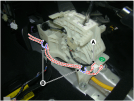
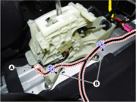
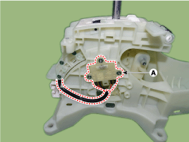
Disconnect the connector (A) from the shift lever.
|
| 5. |
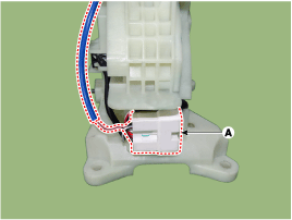
Disconnect the wiring mounting clips (B).
|
| 6. |
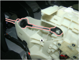
Disconnect the control cable.
|
| 7. |
Remove the bolts and then shift lever assembly (A).
|
| 8. |
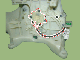
Remove the P position switch mounting bracket (A).
|
| 9. |
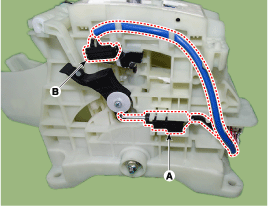
Disconnect the P position switch (B) and shift lock solenoid (A).
|
| 10. |
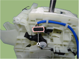
Disconnect the manual mode switch housing (A).
|
| 11. |
Disconnect the main connector (A) from the shift lever.
|
| 12. |
P position switch, shift lock solenoid, manual mode switch housing,
main connector assembly (A).
|
| 13. |
Remove the mounting bracket (A) of terminals from the main connector.
|
| 14. |
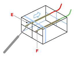
Remove each terminals (F) of the P position switch (A), shift lock solenoid
(B), manual mode switch housing (C) after released lock (E) from the
main connector (D).
|
| [LHD] |
| 15. |
Disconnect a boots from the console upper cover.
|
| 16. |
Pull the knob (A) in the direction of "F" and remove the knob.
|
| 17. |
Remove the floor console assembly.
(Refer to Body - "Floor Console")
|
| 18. |
Disconnect the connector (A) from the shift lever.
|
| 19. |
Disconnect the wiring mounting clips (B).
|
| 20. |
Disconnect the control cable.
|
| 21. |
Remove the bolts and then shift lever assembly (A).
|
| 22. |
Remove the P position switch mounting bracket (A).
|
| 23. |
Disconnect the P position switch (B) and shift lock solenoid (A).
|
| 24. |
Disconnect the manual mode switch housing (A).
|
| 25. |
Disconnect the main connector (A) from the shift lever.
|
| 26. |
P position switch, shift lock solenoid, manual mode switch housing,
main connector assembly (A).
|
| 27. |
Remove the mounting bracket (A) of terminals from the main connector.
|
| 28. |
Remove each terminals (F) of the P position switch (A), shift lock solenoid
(B), manual mode switch housing (C) after released lock (E) from the
main connector (D).
|
| Installation |
| 1. |
To install, reverse the removal procedure.
|
 Inhibitor Switch
Description and operation
Description
•
The inhibitor switch mounted on the upper of transaxle and connected
with shifter lever.
•
...
 Shift Cable
Components and components location
Components
1. Shift lever knob & boots
2. Shift lever assembly
3. Shift cable
4. Manual control lever
5. shift cabl ...
Other information:
Hyundai Creta GS 2014-2025 Service Manual: Specifications
Specification
Items
Inner side
Outer side
Front driveshaft
Joint type
TJ
BJ
Max. permissible angle
23°
46.5°
Tightening torque
...
Hyundai Creta GS 2014-2025 Service Manual: Instrument Cluster
Components and components location
Components
[Standard]
[Supervision]
Connector Pin Information
No
Description
No
Description
1
GND
21
Trip ...
© 2017-2025 www.hcrmangs.com


