Hyundai Creta: Smart Key System / Smart Key Unit
Components and components location
| Components |
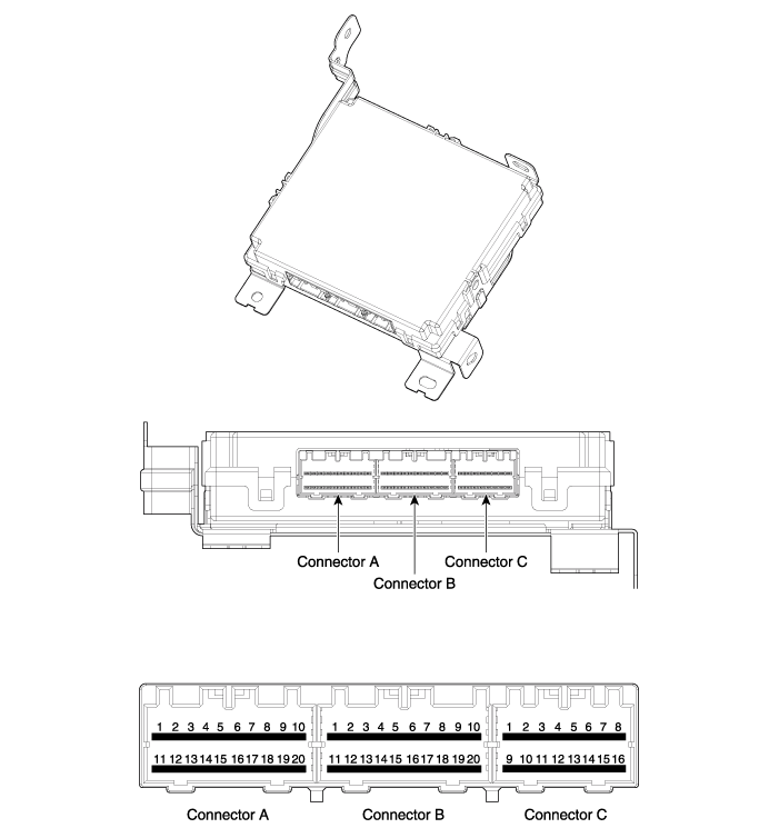
|
No |
Connector A |
Connector B |
Connector C |
|
1 |
BATT (+) |
Driver out side handle antenna (Ground) |
ESCL (ground) |
|
2 |
BATT (+) |
Driver out side handle antenna (Power) |
ESCL Unlock switch |
|
3 |
IGN 1 |
- |
ESCL Enable |
|
4 |
IGN 2 relay |
Body CAN (High) |
- |
|
5 |
IGN 1 relay |
Body CAN (Low) |
SSB Illumination (Blue) |
|
6 |
- |
Wheel speed sensol |
SSB Illumination (Amber) |
|
7 |
- |
Inhibit P (AT Only) Clutch switch (MT Only) |
SSB Illumination (+) |
|
8 |
Interior antenna 2 (Ground) |
- |
SSB Illumination (-) |
|
9 |
Interior antenna 1 (Ground) |
Chassis CAN (Low) |
Immobilizer antenna (Ground) |
|
10 |
Bumper antenna (Ground) |
Chassis CAN (High) |
Immobilizer antenna (Power) |
|
11 |
ACC |
Ground |
- |
|
12 |
IGN 2 |
Ground |
Start feedback |
|
13 |
ACC relay |
- |
Stop lamp fuse |
|
14 |
Start relay |
Driver out side handle switch |
Brake switch |
|
15 |
ESCL (+) |
- |
- |
|
16 |
- |
EMS_communication |
Exterior buzzer |
|
17 |
- |
ESCL_communication |
|
|
18 |
Interior antenna 2 (Power) |
RPM |
|
|
19 |
Interior antenna 1 (Power) |
SSB switch 2 |
|
|
20 |
Bumper antenna (Power) |
SSB switch 1 |
Schematic diagrams
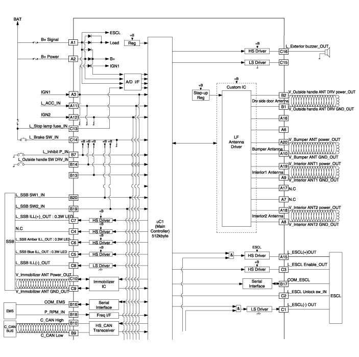
| Circuit Diagram |
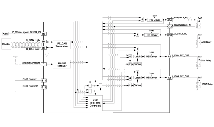
Repair procedures
| Removal |
| 1. |
Disconnect the negative (-) battery terminal.
|
| 2. |
Remove the glove box.
(Refer to Body - "Glove Box Housing")
|
| 3. |
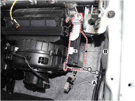
Remove the smart key unit (B) after loosening the mounting bolts(2EA)
and disconnecting the connector (A).
|
| 1. |
Disconnect the negative (-) battery terminal.
|
| 2. |
Remove the console rear complete assembly.
(Refer to Body - "Floor Console Assembly")
|
| 3. |
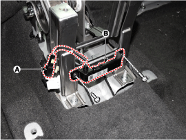
Remove the interior 1 antenna (B) after loosening the mounting nuts
(2EA) and disconnecting the connector (A).
|
| 1. |
Disconnect the negative (-) battery terminal.
|
| 2. |
Remove the rear transvers trim.
(Refer to Body - "Trunk Trim")
|
| 3. |
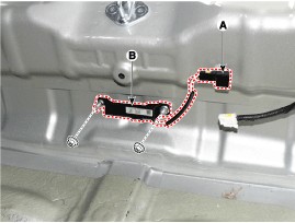
Remove the interior 2 antenna (B) after loosening the mounting nuts(2EA)
and disconnecting the connector (A).
|
| 1. |
Disconnect the negative (-) battery terminal.
|
| 2. |
Remove the rear bumper cover.
(Refer to Body - "Rear Bumper Cover")
|
| 3. |
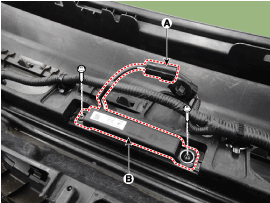
Disconnect the antenna connector (A) on the center of rear bumper.
|
| 4. |
After loosening the screws (2EA), remove the exterior bumper antenna
(B).
|
| 1. |
Disconnect the negative (-) battery terminal.
|
| 2. |
Remove the front left wheel guide.
|
| 3. |
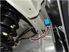
Disconnect the connector (A) then remove the buzzer (B).
|
| 1. |
Disconnect the negative (-) battery terminal.
|
| 2. |
Remove the front door trim.
(Refer to Body - "Front Door Trim")
|
| 3. |
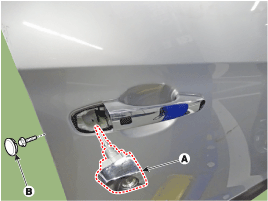
Remove the door outside handle cover (A) after seperating the plug hole
(B) from the door and loosening the mounting bolt.
|
| 4. |
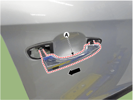
Remove the outside handle (A) by sliding it rearward.
|
| 5. |
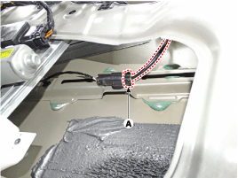
Disconnect the front door outside handle connector (A) and then remove
the wiring mounting clips.
|
| 1. |
Disconnect the negative (-) battery terminal.
|
| 2. |
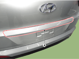
Remove the tailgate trim.
(Refer to Body - "Tailgate Trim")
|
| 3. |
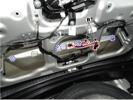
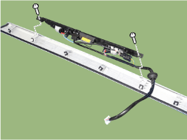
Remove the tailgate garnish (A) disconnecting the connectors (B) and
loosenng the mounting nuts.
|
| 4. |
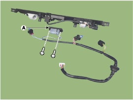
Remove the tailgate switch (A) after seperating the license lamp wiring.
|
| Inspection |
| 1. |
Remove the front door trim.
(Refer to Body - "Front Door Trim")
|
| 2. |
Disconnect the front door outside handle connector.
|
| 3. |
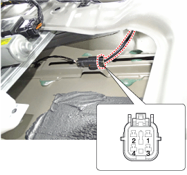
Check for continuity between terminals No 1 and No 3.
|
| 1. |
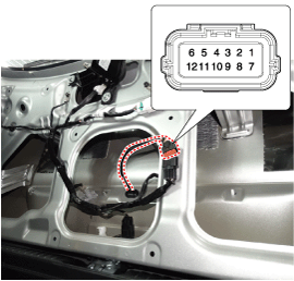
Check for continuity between the tailgate switch terminals.
|
| 2. |
If continuity is not specified, inspect the switch
|
| Installation |
| 1. |
Install the smart key unit.
|
| 2. |
Install the smart key unit mounting bolts and connect the connector.
|
| 3. |
Install the driver side crash pad lower panel.
|
| 4. |
Install the negative (-) battery terminal and check the smart key system.
|
| 1. |
Install the interior 1 antenna.
|
| 2. |
Install the console rear complete assembly.
|
| 3. |
Install the negative (-) battery terminal and check the smart key system.
|
| 1. |
Install the interior 2 antenna.
|
| 2. |
Install the rear transvers trim.
|
| 3. |
Install the negative (-) battery terminal and check the smart key system.
|
| 1. |
Install the exterior bumper antenna.
|
| 2. |
Install the rear bumper cover.
|
| 3. |
Install the negative (-) battery terminal and check the smart key system.
|
| 1. |
Install the buzzer.
|
| 2. |
Install the front left wheel guide.
|
| 3. |
Install the negative (-) battery terminal and check the smart key system.
|
| 1. |
Install the outside handle.
|
| 2. |
Install the door trim.
|
| 3. |
Install the negative (-) battery terminal and check the smart key system.
|
| 1. |
Install the tailgate switch.
|
| 2. |
Install the tailgate garnish.
|
| 3. |
Install the tailgate trim.
|
| 4. |
Install the negative (-) battery terminal and check the smart key system.
|
 Smart Key: Repair procedures
Smart Key
Smart Key Code Saving
1.
Connect the DLC cable of GDS to the data link connector (16 pins) in
driver side crash pad lower panel, turn the power on GD ...
 Smart Key Diagnostic: Repair procedures
Inspection
Self Diagnosis with GDS
Smart key system defects can be quickly diagnosed with the GDS. GDS operates
actuator quickly to monitor, input/output value and self diagnosi ...
Other information:
Hyundai Creta GS 2014-2025 Owners Manual: Changing the coolant
We recommend that the coolant be
replaced by an authorized HYUNDAI
dealer.
NOTICE
Put a thick cloth or fabric around the
radiator cap before refilling the
coolant in order to prevent the
coolant from overflowing into engine
parts such as the alternator.
WARNING
Do not use radiator ...
Hyundai Creta GS 2014-2025 Service Manual: Crankshaft Position Sensor (CKPS)
Description and operation
Description
Crankshaft Position Sensor (CKPS) detects the crankshaft position and is one
of the most important sensors of the engine control system. If there is no CKPS
signal input, fuel is not supplied.That is, vehicle can't run without CKPS sig ...

