Hyundai Creta: Clutch System / Clutch Cover And Disc
Components and components location
| Components |
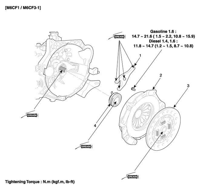
| 1. Clutch release fork 2. Clutch cover assembly |
3. Clutch disk assembly 4. Clutch release bearing |
Repair procedures
| Removal |
| 1. |
Remove the transaxle assembly.
(Refer to Manual Transaxle System - "Manual Transaxle")
|
| 2. |
Remove the clutch cover bolts. Be careful not to be bent or twist bolts.
Loosen bolts in diagonal directions.
|
| Inspection |
| 1. |
Inspect diaphragm spring wear which is in contact with a concentric
slave cylinder bearing.
|
| 2. |
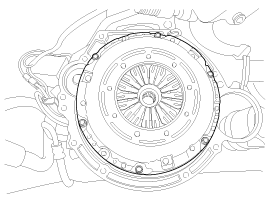
Check the clutch cover and disc surface for wear or cracks.
|
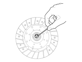
| 3. |
Check the clutch disc lining for slipping or oil marks.
|
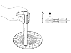
| 4. |
Measure the depth from a clutch lining surface to a rivet. If the measured
value is less than the specification below, replace it.
|
| Installation |
|

| 1. |
Replace a clutch cover and disc as a set.
|
| 2. |
Apply grease on a disc spline part and transaxle input shaft spline
part as required.
|
| 3. |
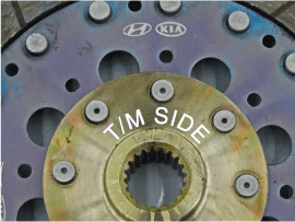
The 'T/M SIDE' marked surface should face transaxle.
|
| 4. |
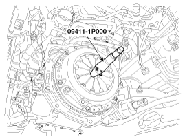
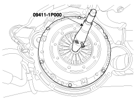
Install the clutch disc and the cover with SST(No.: 09411-1P000).
|
| 5. |
Install the clutch cover bolts. Not to be bent or twisted, Tighten them
in diagonal directions.
|

| 6. |
Install the manual transaxle assembly.
(Refer to Manual Transaxle System - "Manual Transaxle")
|
 Clutch System
...
 Ignition Lock Switch
Specifications
Specifications
Item
Specifications
Working voltage
DC 12V
Operating force
Initial posi ...
Other information:
Hyundai Creta GS 2014-2019 Service Manual: Rear Coil Spring
Components and components location
Components
1. Spring lower pad
2. Spring
3. Spring upper pad
Repair procedures
Removal
1.
Loosen the wheel nuts slightly.
Raise the vehicle, and make sure it is securely s ...
Hyundai Creta GS 2014-2019 Service Manual: Components and components location
Components
1. Front door inside handle hole
cap
2. Front door quadrant inner cover
3. Front door trim
4. Front door belt inside weatherstrip
5. Front door panel
6. Front door belt outside weatherstrip
7. Front door body side weatherstrip
8. ...
© 2017-2026 www.hcrmangs.com
