Hyundai Creta: Power Windows / Power Window Motor
Components and components location
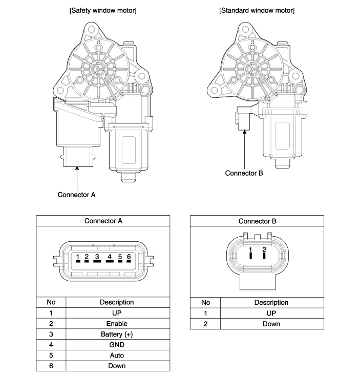
| Components |
Schematic diagrams
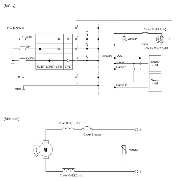
| Schematic Diagrams |
Repair procedures
| Inspection |
| 1. |
Disconnect the negative (-) battery terminal.
|
| 2. |
Remove the front door trim.
(Refer to Body - "Front Door Trim")
|
| 3. |
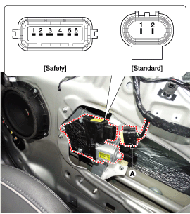
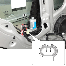
Disconnect the connector (A) from the motor.
|
| 4. |
Connect positive (+) battery cables to terminal No.2 and No.3 negative
(-) battery cables to terminal No.4 respectively.
|
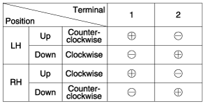
| 5. |
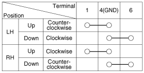
Check that the motor operates normally when connecting the terminals
as shown below.
[Safety Window Motor]
|
| 6. |
Connect the motor terminals directly to battery voltage (12V) and check
that the motor operates smoothly. Next, reverse the polarity and check
that the motor operates smoothly in the reverse direction. If the operation
is abnormal, replace the motor.
[Standard Power Window]
|
| 1. |
Disconnect the negative (-) battery terminal.
|
| 2. |
Remove the rear door trim.
(Refer to Body - "Rear Door Trim")
|
| 3. |
Disconnect the connector (A) from the motor.
|
| 4. |
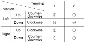
Connect the motor terminals directly to battery voltage (12V) and check
that the motor operates smoothly. Next, reverse the polarity and check
that the motor operates smoothly in the reverse direction. If the operation
is abnormal, replace the motor.
|
| Removal |
| 1. |
Disconnect the negative (-) battery terminal.
|
| 2. |
Remove the front door trim.
(Refer to Body - "Front Door Trim")
|
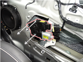
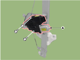
| 3. |
Disconnect the connector (A) from the motor.
|
| 4. |
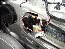
Remove the power window motor (A) after loosening the mounting bolts.
|
| 1. |
Disconnect the negative (-) battery terminal.
|
| 2. |
Remove the front door trim.
(Refer to Body - "Front Door Trim")
|
| 3. |
Remove the rear door power window regulator assembly.
(Refer to Body - "Rear Door Power Window Regulator")
|
| 4. |
Remove the power window motor (A) after loosening the mounting bolts.
|
| Installation |
| 1. |
Install the front power window motor after connecting the connector.
|
| 2. |
Install the front door trim.
|
| 3. |
Connect the negative (-) battery terminal.
|
| 1. |
Install the rear power window motor after connecting the connector.
|
| 2. |
Install the rear door power window regulator assembly.
|
| 3. |
Install the front door trim.
|
| 4. |
Connect the negative (-) battery terminal.
|
 Description and operation
Function of Safety Power
Window
When driver door power window auto-up switch is operated, safety function is
activated.
1.
Safety function condition
...
 Power Window Switch
Components and components location
Components
[Main Power Window Switch]
[Passenger / Rear Power
Window Switch]
Schematic diagrams
Circu ...
Other information:
Hyundai Creta GS 2014-2019 Owners Manual: Wheel alignment and tire balance
The wheels on your vehicle were
aligned and balanced carefully at the
factory to give you the longest tire life
and best overall performance.
In most cases, you will not need to
have your wheels aligned again.
However, if you notice unusual tire
wear or your vehicle pulling one way
or ...
Hyundai Creta GS 2014-2019 Owners Manual: If the engine overheats
If your temperature gauge indicates
overheating, you experience a loss
of power, or hear loud pinging or
knocking, the engine may be overheating.
If this happens, you should:
1. Pull off the road and stop as soon
as it is safe to do so.
2. Place the shift lever in P (Park, for
automati ...
