Hyundai Creta: Smart Key System / Smart Key Diagnostic: Repair procedures
Hyundai Creta GS 2014-2026 Service Manual / Body Electrical System / Smart Key System / Smart Key Diagnostic: Repair procedures
| Inspection |
Self Diagnosis with GDS
Smart key system defects can be quickly diagnosed with the GDS. GDS operates
actuator quickly to monitor, input/output value and self diagnosis.
The following three features will be major problem in SMART KEY system.
| 1. |
Problem in SMART KEY unit input.
|
| 2. |
Problem in SMART KEY unit.
|
| 3. |
Problem in SMART KEY unit output.
|
The following three diagnostic solutions will be the main solution process to
a majority of concerns.
| 4. |
SMART KEY unit Input problem : switch diagnosis
|
| 5. |
SMART KEY unit problem : communication diagnosis
|
| 6. |
SMART KEY unit Output problem : antenna and switch output diagnosis
|
Switch Diagnosis
| 1. |
Connect the cable of GDS to the data link connector in driver side crash
pad lower panel, turn the power on GDS.
|
| 2. |
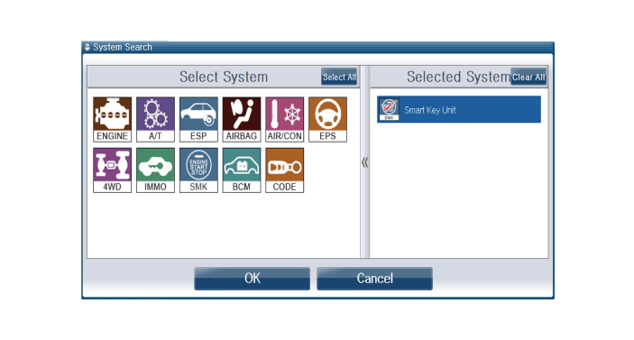
Select the vehicle model and then SMART KEY system.
|
| 3. |
Select the "Smart Key Unit".
|
| 4. |
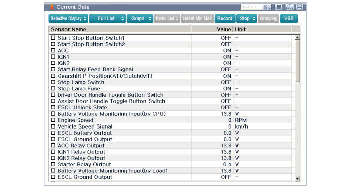
After IG ON, select the "Current Data".
|
| 5. |
You can see the situation of each switch on scanner after connecting
the "Current Data" process.
|
Communication Diagnosis with GDS (Self Diagnosis)
| 1. |
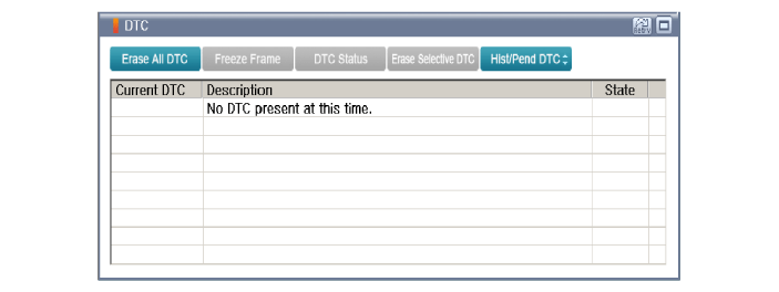
Communication diagnosis checks that the each linked components operates
normal.
|
| 2. |
Connect the cable of GDS to the data link connector in driver side crash
pad lower panel.
|
| 3. |
After IG ON, select the "DTC".
|
Antenna Actuation Diagnosis
| 1. |
Connect the cable of GDS to the data link connector in driver side crash
pad lower panel.
|
| 2. |
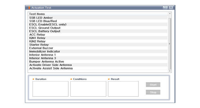
After IG ON, select the "Actuation Test".
|
| 3. |
Set the smart key near the related antenna and operate it with a GDS.
|
| 4. |
If the LED of smart key is blinking, the smart key is normal.
|
| 5. |
If the LED of smart key is not blinking, check the voltage of smart
key battery.
|
| 6. |
Antenna actuation
|
Antenna Status Check
| 1. |
Connect the cable of GDS to the data link connector in driver side crash
pad lower panel.
|
| 2. |
Select the "Antenna Status Check".
|
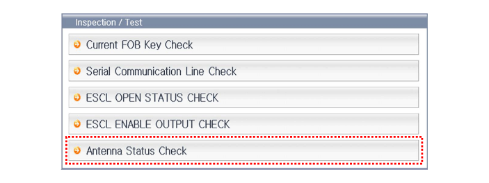
| 3. |
After IG ON, select the "Antenna Status Check".
|
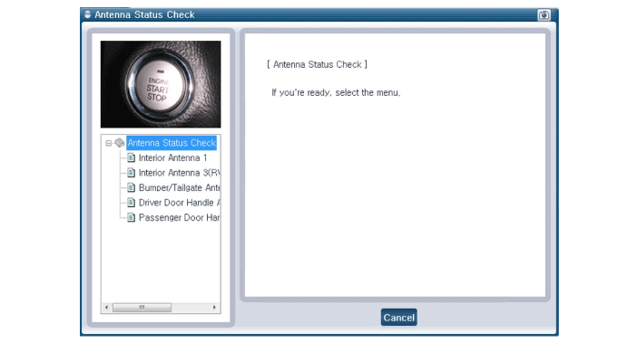
| 4. |
Set the smart key near the related antenna and operate it with a GDS.
|
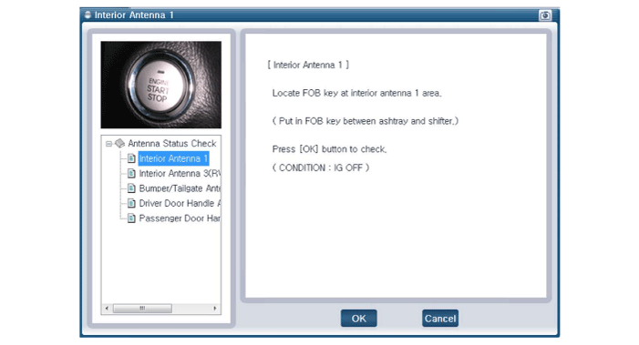
| 5. |
If the smart key runs normal , the related antenna, smart key(transmission,
reception) and exterior receiver are normal.
|
| 6. |
Antenna status
|
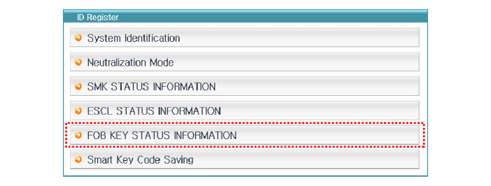
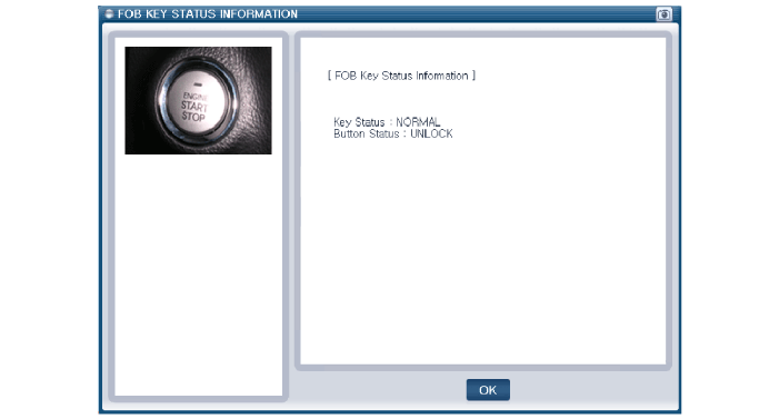
FOB Status Check
| 1. |
Connect the cable of GDS to the data link connector in driver side crash
pad lower panel.
|
| 2. |
After IGN ON, select the "FOB Key Status INFO".
|
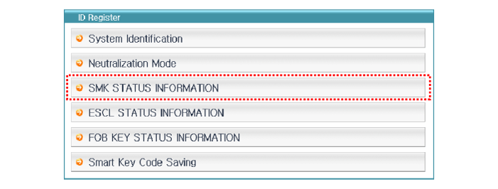
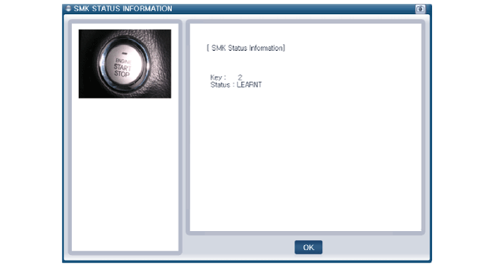
Smart Key Status Check
| 1. |
Connect the cable of GDS to the data link connector in driver side crash
pad lower panel.
|
| 2. |
After IG ON, select the "SMK Status INFO".
|
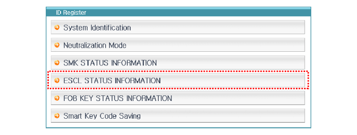
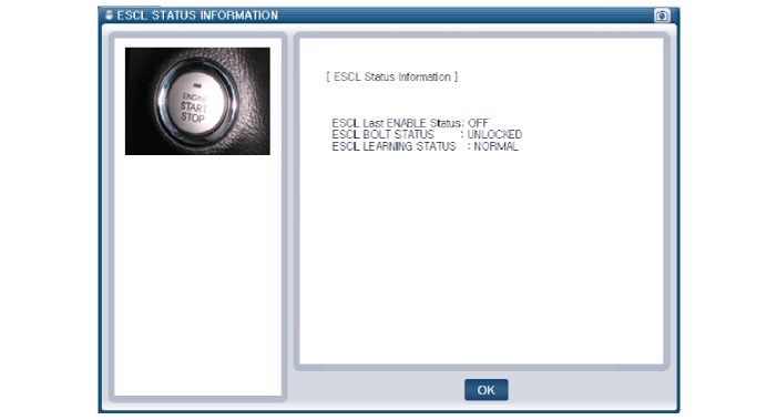
ESCL Status Check
| 1. |
Connect the cable of GDS to the data link connector in driver side crash
pad lower panel.
|
| 2. |
After IGN ON, select the "ESCL Status INFO".
|
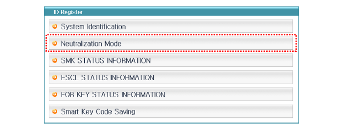
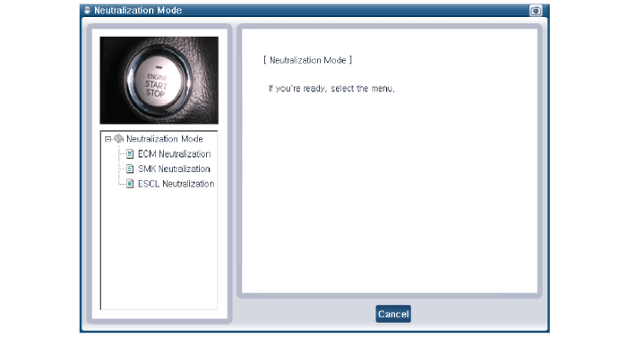
Neutralization Status Check
| 1. |
Connect the cable of GDS to the data link connector in driver side crash
pad lower panel.
|
| 2. |
After IGN ON, select the "Neutralization Mode".
|
Input Switch List
|
No |
Item name |
Unit |
|
1 |
SSB switch2 |
- |
|
2 |
ACC |
- |
|
3 |
IGN1 |
- |
|
4 |
Gear 'P' Position |
- |
|
5 |
Brake switch |
- |
|
6 |
FL Door Lock Button |
- |
|
7 |
FR Door Lock Button |
- |
|
8 |
Trunk Lid switch |
- |
|
9 |
Battery Voltage |
- |
|
10 |
Alternator Voltage |
- |
|
11 |
KEY out Indicator Lamp |
- |
|
12 |
Immobilizer Lamp |
- |
|
13 |
External Buzzer |
- |
|
14 |
ESCL Enable |
- |
Actuator List
|
No |
Item name |
Condition |
|
1 |
Immo.indicator Lamp |
Ignition switch ON Engine off |
|
2 |
External Buzzer |
Ignition switch ON Engine off |
|
3 |
Interior Antenna 1 Active |
Ignition switch ON Engine off |
|
4 |
Interior Antenna 2 Active |
Ignition switch ON Engine off |
|
5 |
Bumper Antenna Active |
Ignition switch ON Engine off |
|
6 |
DRV DR Antenna Active |
Ignition switch ON Engine off |
|
7 |
AST DR Antenna Active |
Ignition switch ON Engine off |
 Smart Key Unit
Components and components location
Components
Connector Pin Information
No
Connector A
Connector B
Connector C
...

Other information:
Hyundai Creta GS 2014-2026 Owners Manual: Wipers and washers
A : Wiper speed control (front)
/ MIST – Single wipe
O / OFF – Off
--- / INT – Intermittent wipe
AUTO* – Auto control wipe
1 / LO– Low wiper speed
2 / HI – High wiper speed
B : Intermittent control wipe time
adjustment
C : Wash with brief wipes (front)
D : Rear wip ...
Hyundai Creta GS 2014-2026 Service Manual: Components and components location
Components
1. Roof trim
2. Sunvisor [LH]
3. Sunvisor [RH]
4. Assist handle
...
© 2017-2026 www.hcrmangs.com
