Hyundai Creta: Brake System / Stop Lamp Switch
Components and components location
| Components Location |
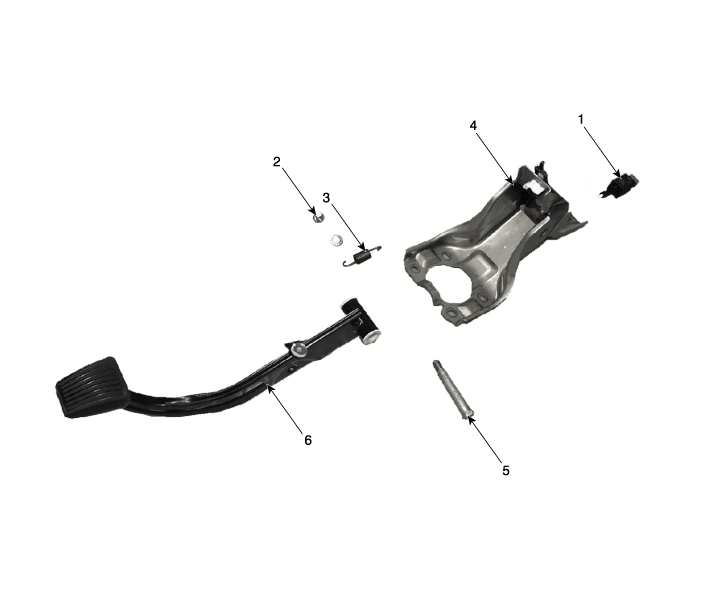
| 1.Stop lamp switch 2. Nut 3. Return spring |
4. Brake pedal member assembly 5. Bolt 6. Brake pedal arm |
Description and operation
| Description |
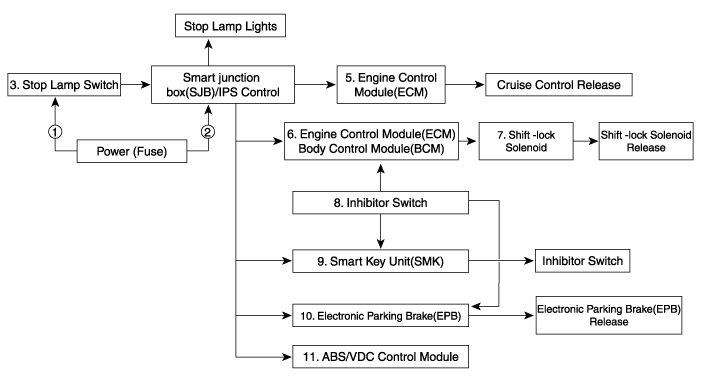
Schematic diagrams
| Schematic Diagram |
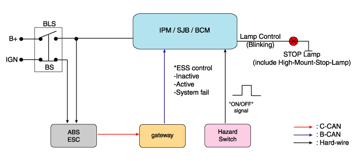
| System circuit diagram |
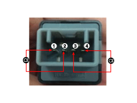
| Terminal function |

|
Teminal |
Description |
|
1 |
IGN1 |
|
2 |
Engine Control Module (ECM) |
|
3 |
B+ |
|
4 |
Stop Lmap |
Troubleshooting
| Troubleshooting |
| 1. |
Part diagnosis
|
| 2. |
Symptom diagnosis
|
| 3. |
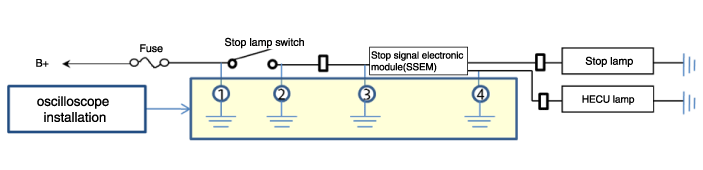
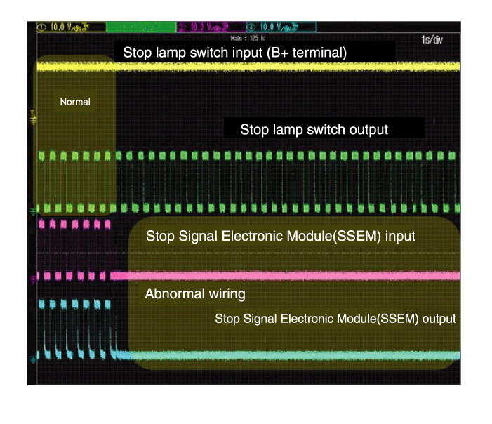
Stop lamp switch system diagnosis
SSEM : Stop Signal Electronic Module
|
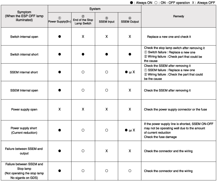
| 4. |
Refer to DTC guide when the related DTC codes are displayed.
|
Repair procedures
| Adjustment |
| 1. |
Turn ignition switch OFF and disconnect the negative (-) battery cable.
|
| 2. |
Remove the lower crash pad.
(Refer to Body - "Crash Pad")
|
| 3. |
Remove the knee airbag.
(Refer to Rstraint - "Air Bag Module")
|
| 4. |
Confirm the gap between stop lamp switch and bracket.
|
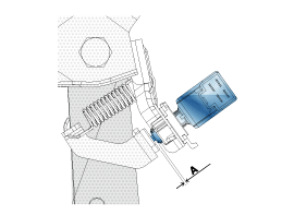
| 5. |
If the gap between stop lamp switch and bracket is not 1.0~2.0mm(0.04~0.08in),
check the mounting clip and other part of around stop lamp.
|
| 6. |
If there is normal, remove the stop lamp switch and then install again.
|
| Inspection |
| 1. |
Analyze GDS data and confirm if there is anything wrong with the stop
lamp switch.
|
| Removal |
| 1. |
Turn ignition switch OFF and disconnect the negative (-) battery cable.
|
| 2. |
Remove the lower crash pad.
(Refer to Body - "Crash Pad")
|
| 3. |
Remove the knee airbag.
(Refer to Rstraint - "Air Bag Module")
|
| 4. |
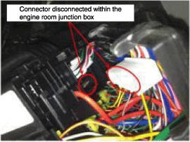
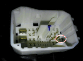
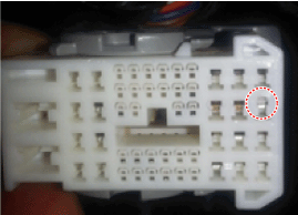
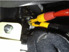
Disconnect the stop lamp switch connector (A).
|
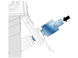
| 5. |
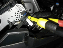
Pull the locking plate (A) as indicated by the arrow.
|
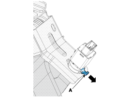
| 6. |
Turn stop lamp switch 45° counterclockwise and remove it.
|
| 7. |
Inspect a removed stop lamp switch along the below procedures.
|
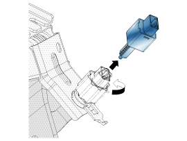
| Installation |
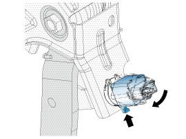
| 1. |
Fix the brake pedal arm and insert fully the stop lamp switch as hiding
contact part.
|
| 2. |
After inserting, turn the stop switch (A) 45° clockwise, and then assemble
locking plate (B) by pushing.
|
| 3. |
Confirm the gap between stop lamp switch and bracket.
|

| 4. |
Connect the stop lamp switch connector.
|
| 5. |
Install the knee air bag.
(Refer to Restraint - "Knee Airbag (KAB) Module")
|
| 6. |
Install the lower crash pad.
(Refer to Body - "Crash Pad")
|
 Rear Disc Brake
Components and components location
Components
1. Adjuster assembly
2. Upper return spring
3. Lever pawl
4. Shoe hold pin
5. Shoe hold spring
6. Shoe ho ...

Other information:
Hyundai Creta GS 2014-2026 Owners Manual: Installing a Child Restraint
System (CRS)
WARNING
Before installing your Child
Restraint System always:
Read and follow the instructions
provided by the manufacturer of
the Child Restraint System.
Failure to follow all warnings and
instructions could increase the risk
of the SERIOUS INJURY or
DEATH if an accident occurs.
WAR ...
Hyundai Creta GS 2014-2026 Service Manual: Steering Column Shroud Panel
Components and components location
Component Location
1. Steering column shroud lower
panel
2. Steering column shroud upper
panel
Repair procedures
Replacement
[Steering column shroud lower panel]
...
