Hyundai Creta: Brake System / Rear Disc Brake
Components and components location
| Components |
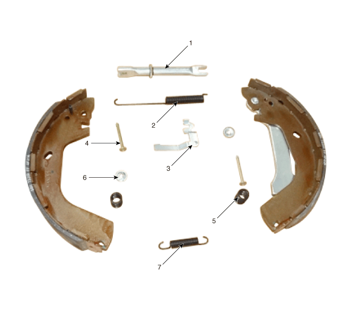
| 1. Adjuster assembly 2. Upper return spring 3. Lever pawl 4. Shoe hold pin |
5. Shoe hold spring 6. Shoe hold washer 7. Lower return spring |
Repair procedures
| Removal |
| 1. |
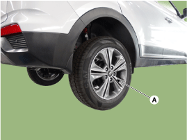
Loosen the wheel nuts slightly. Raise the vehicle, and make sure it
is securely supported.
|
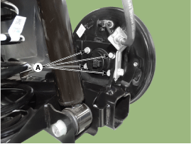
| 2. |
Remove the rear wheel & tire (A).
|

| 3. |
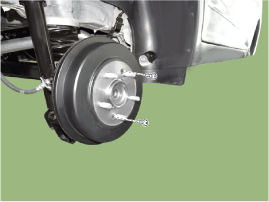
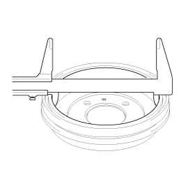
Loosen the screw and then remove the drum.
|
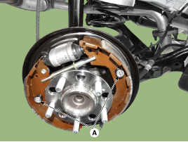
| 4. |
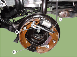
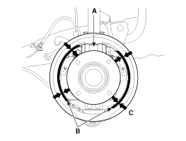
Remove the upper shoe return spring (A), lower shoe return spring (B),
level pawl (C) and djuster assembly (D).
|
| 5. |
Remove the shoe hold assembly (A) and then remove the brake shoe.
|
| 6. |
Disconnect the parking cable.
|
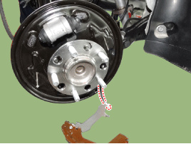
| 7. |
Disconnect the brake fluid tube flare nut(A).
|
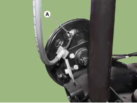
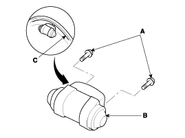
| 8. |
Loosen the mounting bolts (A) and then remove the wheel cylinder (B)
from the backing plate (C).
|
| 9. |
Loosen the hub mounting bolts (A) and then remove the backing plate.
|
| 10. |
Install in the reverse order of removal.
|
| 11. |
After installation, bleed the brake system.
(Refer to Brake System - "Brake system bleeding")
(Refer to Brake System - "ESP system bleeding")
(Refer to Brake System - "ABS system bleeding")
|
| Inspection |
|

|
| 1. |
Raise the rear of the vehicle, and make sure it is securely supported.
|
| 2. |
Release the parking brake, and remove the rear brake drum.
|
| 3. |
Check the wheel cylinder (A) for leakage.
|
| 4. |
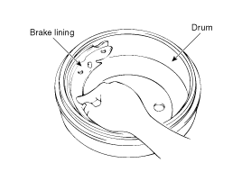
Check the brake linings (B) for cracking, glazing, wear, and contamination.
|
| 5. |
Measure the brake lining thickness (C). Measurement does not include
brake shoe thickness.
|
| 6. |
If the brake lining thickness is less than the service limit, replace
the brake shoes as a set.
|
| 7. |
Check the bearings in the hub unit for smooth operation. If it requires
servicing, replace it.
|
| 8. |
Measure the inside diameter of the brake drum with inside vernier calipers.
|
| 9. |
If the inside diameter of the brake drum is more than the service limit,
replace the brake drum.
|
| 10. |
Check the brake drum for scoring, grooves, and cracks.
|
| 11. |
Inspect the brake lining and drum for proper contact.
|
| 12. |
Inspect the wheel cylinder outside for excessive wear and damage.
|
| 13. |
Inspect the backing plate for wear or damage.
|
 Front Disc Brake
Components and components location
Components
1. Caliper carrier
2. Pad retainer
3. Brake pad
4. Inner pad shim
5. Pad return spring
6. Caliper body
...
 Stop Lamp Switch
Components and components location
Components Location
1.Stop lamp switch
2. Nut
3. Return spring
4. Brake pedal member assembly
5. Bolt
6. Brake pedal ...
Other information:
Hyundai Creta GS 2014-2019 Service Manual: Tail Gate Latch
Components and components location
Component Location
1. Tail gate latch assembly
Repair procedures
Replacement
ŌĆó
Put on gloves to protect yo ...
Hyundai Creta GS 2014-2019 Owners Manual: Battery capacity label
ŌØł The actual battery label in the vehicle
may differ from the illustration.
1. MF45L-BCI : The HYUNDAI model
name of battery
2. 12V : The nominal voltage
3. 45Ah(20HR) : The nominal capacity
(in Ampere hours)
4. 80RC : The nominal reserve
capacity (in min.)
5. 410CCA : The cold-test ...
┬® 2017-2026 www.hcrmangs.com
