
Hyundai Creta: Engine Control System / Components and components location
Hyundai Creta GS 2014-2019 Service Manual / Engine Control / Fuel System / Engine Control System / Components and components location
| Components Location |
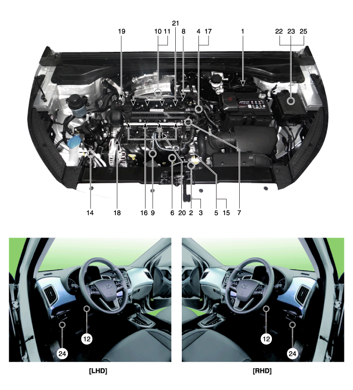
| 1. ECM (Engine Control Module) 2. Manifold Absolute Pressure Sensor (MAPS) 3. Intake Air Temperature Sensor (IATS) 4. Engine Coolant Temperature Sensor (ECTS) 5. Throttle Position Sensor (TPS) [integrated into ETC Module] 6. Crankshaft Position Sensor (CKPS) 7. Camshaft Position Sensor (CMPS) [Bank 1 / Intake] 8. Camshaft Position Sensor (CMPS) [Bank 1 / Exhaust] 9. Knock Sensor (KS) 10. Heated Oxygen Sensor (HO2S) [Bank 1/Sensor 1] 11. Heated Oxygen Sensor (HO2S) [Bank 1/Sensor 2] 12. Accelerator Position Sessor (APS) |
13. Vehicle Speed Sensor (VSS) 14. A/C Pressure Transducer (APT) 15. ETC Motor [integrated into ETC Module] 16. Injector 17. Purge Control Solenoid Valve (PCSV) 18. CVVT Oil Control Valve (OCV) [Bank 1 / Intake] 19. CVVT Oil Control Valve (OCV) [Bank 1 / Exhaust] 20. Variable Intake Solenoid (VIS) Valve 21. Ignition Coil 22. Main Relay 23. Fuel Pump Relay 24. Data Link Connector (DLC) [16 pin] 25. Multi-Purpose Connector [6 pin] |
|
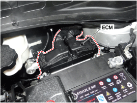
1. ECM (Engine Control Module) |
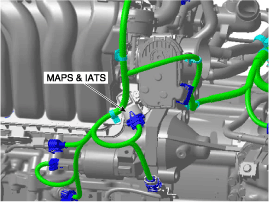
2. Manifold Absolute Pressure Sensor (MAPS) 3. Intake Air Temperature Sensor (IATS) |
|
|
|
|
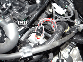
4. Engine Coolant Temperature Sensor (ECTS) |
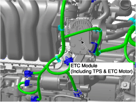
5. Throttle Position Sensor (TPS) [integrated into ETC Module] 15. ETC Motor [integrated into ETC Module] |
|
|
|
|
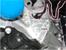
6. Crankshaft Position Sensor (CKPS) |
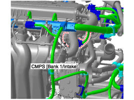
7. Camshaft Position Sensor (CMPS) [Bank 1 / Intake] |
|
|
|
|
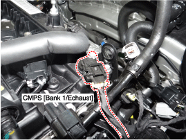
8. Camshaft Position Sensor (CMPS) [Bank 1 / Exhaust] |
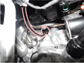
9. Knock Sensor (KS) |
|
|
|
|
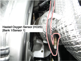
10. Heated Oxygen Sensor (HO2S) [Bank 1/Sensor 1] |
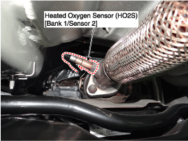
11. Heated Oxygen Sensor (HO2S) [Bank 1/Sensor 2] |
|
|
|
|
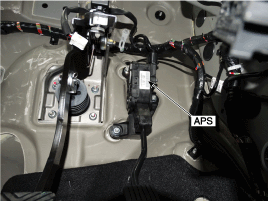
12. Accelerator Position Sessor (APS) |
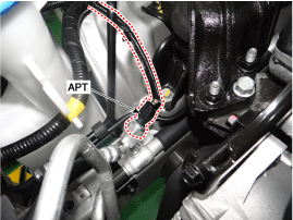
14. A/C Pressure Transducer (APT) |
|
|
|
|
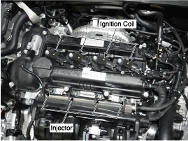
16. Injector 21. Ignition Coil |
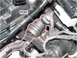
17. Purge Control Solenoid Valve (PCSV) |
|
|
|
|
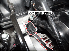
18. CVVT Oil Control Valve (OCV) [Bank 1 / Intake] |
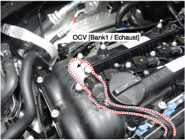
19. CVVT Oil Control Valve (OCV) [Bank 1 / Exhaust] |
|
|
|
|
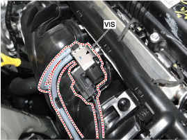
20. Variable Intake Solenoid (VIS) Valve |
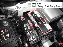
22. Main Relay 23. Fuel Pump Relay 24. Multi-Purpose Check Connector [6pin] |
|
|
|
|
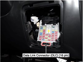
24. Data Link Connector (DLC) [16 pin] |
|
|
|
|
 Description and operation
Description
If the Gasoline Engine Control system components (sensors, ECM, injector, etc.)
fail, interruption to the fuel supply or failure to supply the proper amount
of fuel f ...
 Engine Control Module (ECM)
Schematic diagrams
ECM Terminal And Input/Output
signal [M/T]
ECM Terminal Function
(M/T)
Connector [E100-MA]
Pin No.
Descriptio ...
Other information:
Hyundai Creta GS 2014-2019 Service Manual: Special service tools
Special Service Tools
Tool Name / Number
Illustration
Description
Crankshaft front oil seal installer
09455-21200
Installation of the front oil seal
Valve stem oil seal installer
...
Hyundai Creta GS 2014-2019 Service Manual: Special service tools
Special Service Tools
Tool(Number and Name)
Illustration
Use
09581- 2T100
Piston expander
Spreading the front disc brake piston.
...
В© 2017-2026 www.hcrmangs.com
