Hyundai Creta: ABS(Anti-Lock Brake System) / Description and operation
Hyundai Creta GS 2014-2019 Service Manual / Brake System / ABS(Anti-Lock Brake System) / Description and operation
| Description |
This specification applies to HCU(Hydraulic Control Unit) and ECU(Electronic
Control Unit) of the HECU.(Hydraulic and Electronic Control Unit)
This specification is for the wiring design and installation of ABS/ESP ECU.
This unit has the functions as follows.
| тАУ |
Input of signal from Pressure sensor, Steering angle sensor, Yaw & Lateral
G sensor, the wheel speed sensors attached to each wheel.
|
| тАУ |
Control of braking force / traction force / yaw moment.
|
| тАУ |
Failsafe function.
|
| тАУ |
Self diagnosis function.
|
| тАУ |
Interface with the external diagnosis tester.
|
Installation position : engine compartment
| тАУ |
Brake tube length from Master cylinder port to HECU inlet port should
be max. 1m
|
| тАУ |
The position should not be close to the engine block and not lower than
the wheel.
|
Operation
The ECU shall be put into operation by switching on the operating voltage (IGN).
On completion of the initialization phase, the ECU shall be ready for operation.
In the operating condition, the ECU shall be ready, within the specified limits
(voltage and temperature), to process the signals offered by the various sensors
and switches in accordance with the control algorithm defined by the software
and to control the hydraulic and electrical actuators.
Wheel Sensor Signal Processing
The ECU shall receive wheel speed signal from the four active wheel sensors.
The wheel signals are converted to voltage signal by the signal conditioning
circuit after receiving current signal from active wheel sensors and given as
input to the ECU.
Solenoid Valve Control
When one side of the valve coil is connected to the positive voltage that is
provided through the valve relay and the other side is connected to the ground
by the semiconductor circuit, the solenoid valve goes into operation.
The electrical function of the coils are always monitored by the valve test
pulse under normal operation conditions.
Voltage Limits
| тАУ |
Overvoltage
When overvoltage is detected(above 17 ┬▒ 0.5 V), the ECU switches off
the valve relay and shuts down the system.
When voltage is returned to operating range, the system goes back to
the normal condition after the initialization phase.
|
| тАУ |
Undervoltage
In the event of undervoltage(below 10V), ABS control shall be inhibited
and the warning lamp shall be turned on.
When voltage is returned to operating range, the warning lamp is switched
off and ECU returns to normal operating mode.
|
Pump Motor Checking
The ECU performs a pump motor test at a speed of 15 km/h(9 MPH) once after IGN
is switched on.
Diagnostic Interface
Failures detected by the ECU are encoded on the ECU, stored in a EEPROM and
read out by diagnostic equipment when the ignition switch is turned on.
The diagnosis interface can also be used for testing the ECU during production
of the ECU and for actuating the HCU in the test line of manufactories (Air-bleeding
line or Roll and Brake Test line).
Warning Lamp Module
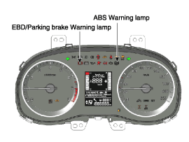
| 1. |
ABS Warning Lamp module
The active ABS warning lamp module indicates the self-test and failure
status of the ABS.
The ABS warning lamp shall be on:
|
| 2. |
PARKING/EBD warning lamp module
The active EBD warning lamp module indicates the self-test and failure
status of the EBD.
However, in case the Parking Brake Switch is turned on, the EBD warning
lamp is always turned on regardless of EBD functions.
The EBD warning lamp shall be on:
|
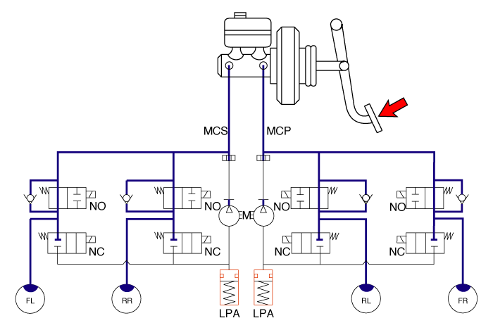
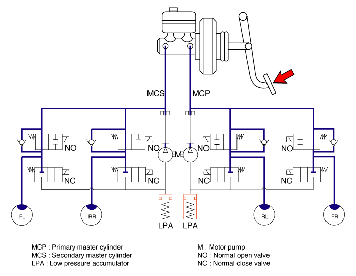
| ABS Control |
| 1. |
NORMAL BRAKING without ABS
Under the normal braking, voltage is not supplied to solenoid valve,
inlet valve is opened and outlet valve is closed. When the brake is
depressed, brake fluid is supplied to the wheel cylinder via solenoid
valve to activate the brake.When the brake is released, brake fluid
is back to the master cylinder via inlet valve and check valve.
|
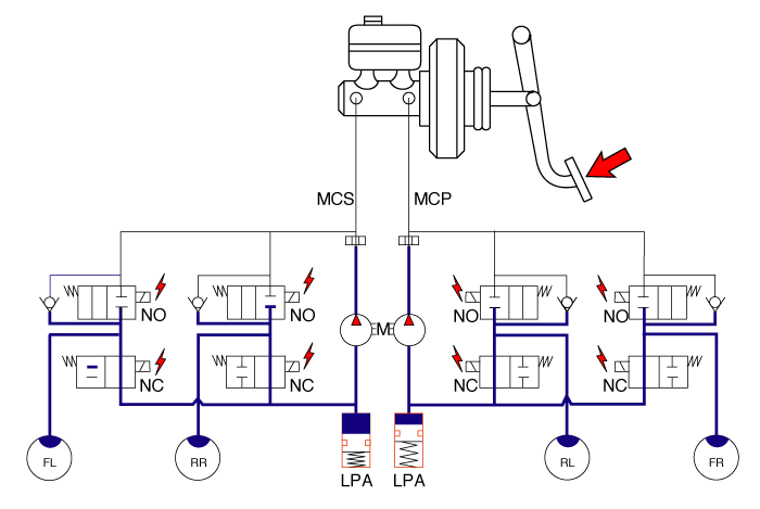
| 2. |
Dump Mode
Under the emergency braking, if the wheels start to lock up, HECU sends
a signal to the solenoid valve to decrease the brake fluid, then voltage
is supplied to each solenoid. At this time inlet valve is closed and
brake fluid is blocked from the master cylinder. Conversely outlet valve
is opened and brake fluid passes through wheel cylinder to reservoir,
resulting in pressure decrease.
|
| 3. |
Hold Mode
When the brake fluid pressure is maximally decreased in wheel cylinder,
HECU sends a signal to solenoid valve to keep the fluid pressure, voltage
is supplied to inlet valve but it is not supplied to outlet valve. At
this time inlet and outlet valves are closed and brake fluid is kept
in wheel cylinder.
|
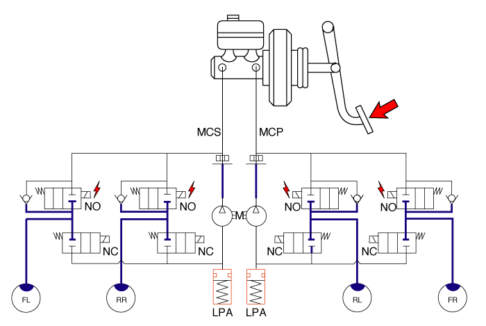
| 4. |
Increase Mode
If HECU determines there's no lock-up in the wheel, HECU cuts voltage
to solenoid valve. So voltage is not supplied to each solenoid valve,
brake fluid passes through the inlet valve to wheel cylinder, resulting
in pressure increase.
|
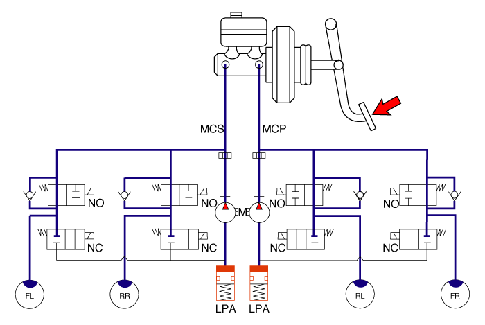
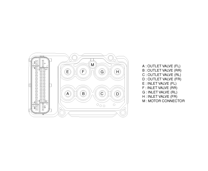
ABS HECU External Diagram
Hydraulic System Diagram
 Components and components location
Components
[LHD]
1. ABS control module (HECU)
2. Front wheel speed sensor
3. Rear wheel speed sensor
4. Steering angle sensor
...
 Schematic diagrams
Schematic diagram
Terminal Function
ABS Connector Input/ Out put
Wire No.
Designation
Current12V(AMPS)
max.pe ...
Other information:
Hyundai Creta GS 2014-2019 Service Manual: Engine Cover: Repair procedures
Removal and Installation
1.
Remove the engine cover (A).
2.
Install in the reverse order of removal.
...
Hyundai Creta GS 2014-2019 Service Manual: Line Pressure Control Solenoid Valve
Description and operation
Description
тАв
Line pressure control solenoid valve is attached to the valve body.
тАв
This variable force solenoid valve indirectly controls the hydraulic
pressure inside the line pressure.
...
┬й 2017-2026 www.hcrmangs.com
