Hyundai Creta: Automatic Transaxle Control System / Inhibitor Switch
Description and operation
| Description |
| • |
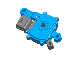
The inhibitor switch mounted on the upper of transaxle and connected
with shifter lever.
|
| • |
The inhibitor switch has four points of contact and it makes the signals
(S1, S2, S3, S4).
|
| • |
The inhibitor switch signals delivered at the TCM according to control
of the shift lever positions (P, R, N, D) and it is used to control
of the gear setting.
|
Specifications
| Specifications |
â–· Type: Combination of output signals from 4 terminals
|
Power supply (V) |
12 |
|
Output type |
Combination of output signals |
Signal Code Table
|
|
P |
P-R |
R |
R-N |
N |
N-D |
D |
|
S1 |
12V |
12V |
0 |
0 |
0 |
0 |
0 |
|
S2 |
0 |
12V |
12V |
12V |
0 |
0 |
0 |
|
S3 |
0 |
0 |
0 |
12V |
12V |
12V |
0 |
|
S4 |
0 |
0 |
0 |
0 |
0 |
12V |
12V |
Schematic diagrams
| Circuit Diagram |
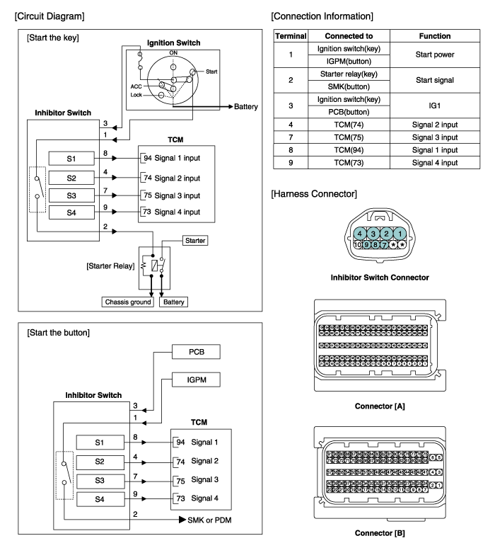
Troubleshooting
| Fault Diagnosis |
| Fault Diagnosis for Symptom |
|
Major Symptom |
Expected Cause |
Items to Check and Measures |
|
Shift lever inoperable |
Faulty shift cable tension |
Adjust shift cable tension (refer to "Automatic Transaxle System – Inhibitor Switch") |
|
Faulty shift cable assembly/connection |
Check manual control valve assembly and re-assemble if necessary. |
|
|
Faulty shift cable bracket installation |
Check cable installation on the shift lever assembly and repair if necessary. |
|
|
Shock when shifting to and from D/R Motor run-up when shifting to and from D/R |
Faulty inhibitor switch "N" setting |
Use the "N" setting jig and adjust the "N" setting. |
|
(refer to "Automatic Transaxle System – Inhibitor Switch") |
||
|
Faulty oil pressure in the valve body. |
Replace valve body assembly or inspect/replace transaxle assembly |
|
|
Faulty engine start Current gear not indicated in the Cluster Warning Lamp ON Engine stall while stopped Creeping not possible Auto parking release disabled |
Faulty CAN terminating resistance/circuit |
Check PCU/battery management system module. |
|
Check PCU wiring connector connection. |
||
|
Faulty power supply (IG.1) to inhibitor switch circuit |
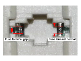
Check for gap on the junction box power terminal in the engine compartment
and fuse (TCU2) connection. Repair terminal or exchange junction box if
necessary. |
|
|
Faulty inhibitor switch circuit fuse |
Check fuse and junction box terminal, and repair. |
|
|
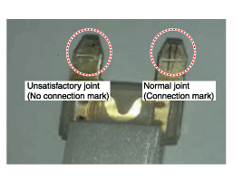
Faulty inhibitor switch wiring connector |
Check for foreign substance in the wiring connector, and check for gap on
the terminal. |
|
|
Check sealing on unused pin, and check for corrosion on the terminal. |
||
|
Faulty reverse lamp circuit |
Check reverse lamp ground, and reassemble if necessary. |
|
|
Faulty inhibitor switch wiring ground |
Check wiring ground, and reassemble if necessary. |
|
|
Faulty inhibitor switch circuit (unused code) |
Inspect in accordance with the inspection flow, then replace inhibitor switch
if necessary. |
|
|
Faulty inhibitor switch operation (faulty mid-range) |
Inspect in accordance with the inspection flow, then replace inhibitor switch
if necessary. |
Repair procedures
| Inspection |
| Inspection flow of the inhibitor switch |
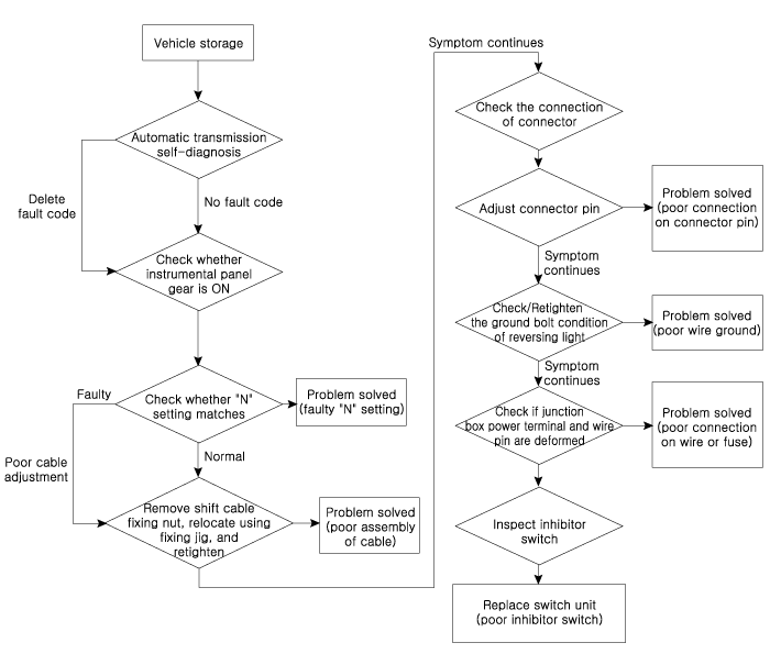
Items to check
| 1. |
Inspect DTC code.
|
| 2. |
Inspect whether N setting matches.
|
| 3. |
Inspect shift cable separation.
|
| 4. |
Inspect whether connector is connected.
|
| 5. |
Inspect ground condition on reversing light circuit.
|
| 6. |
Inspect wiring connection on junction box power terminal and fuse lamp.
|
| 7. |
Inspect inhibitor switch signal.
|
| Removal |
| 1. |
Make sure vehicle does not roll before setting shift lever to "N" position.
|
| 2. |
Disconnect the negative (-) battery cable.
|
| 3. |
Remove the air cleaner assembly and air duct.
(Refer to Engine Mechanical System - "Air cleaner")
|
| 4. |
Remove the battery and battery tray.
(Refer to Engine Electrical System - "Battery")
|
| 5. |
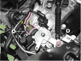
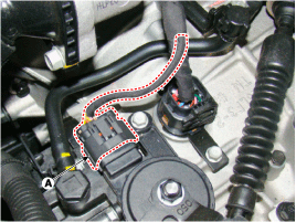
Disconnect the inhibitor switch connector (A).
|
| 6. |
Remove the shift cable mounting nut (B).
|
| 7. |
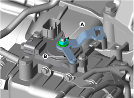
Remove the manual control lever (B) and the washer after removing a
nut (A).
|
| 8. |
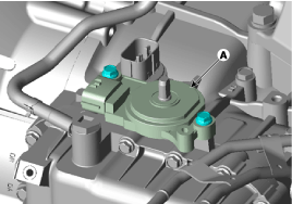
Remove the inhibitor switch (A) after removing the bolts (2ea).
|
| Installation |
| 1. |
Check that the shift lever is placed in the "N" position.
|
| 2. |
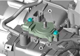
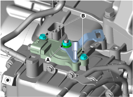
Lightly tighten the bolts (A) after installing the inhibitor switch
(B).
|
| 3. |
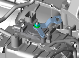
Lightly tighten the nut (A) after installing the manual control lever
(B).
|
| 4. |
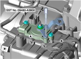
Align the hole (A) in the manual control lever with the "N" position
hole (B) of the inhibitor switch and then insert the inhibitor switch
guide pin (SST No.: 09480-A3800).
|
| 5. |
Tighten the nut (A) and bolts (B) with the specified torque.
|
| 6. |
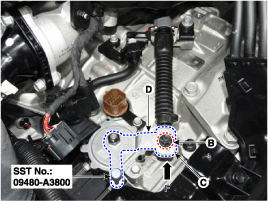
Lightly tighten the nut (B) after connected the shift cable (C) in the
manual control lever (D).
|
| 7. |
Push shift cable (C) lightly to "F" direction shown to eliminate free
play of shift cable.
|
| 8. |
Tighten the nut (B) with the specified torque.
|
| 9. |
Remove the inhibitor switch guide pin (SST No.: 09480-A3800) from the
hole.
|
| 10. |
Connect the inhibitor switch connector (A).
|
| 11. |
Install the battery and battery tray.
(Refer to Engine Electrical System - "Battery")
|
| 12. |
Install the air cleaner assembly and air duct.
(Refer to Engine Mechanical System - "Air cleaner")
|
| 13. |
Connect the battery negative (-) cable.
|
| 14. |
Check that operating surely at each range of the inhibitor switch corresponding
to each position of shift lever.
|
 SS-B Solenoid Valve (ON/OFF)
Description and operation
Description
•
SS-B solenoid valve is attached to the valve body and is an on/off solenoid
valve that is used to change gears.
...
 Shift Lever
Components and components location
Components Location
1. Shift lever knob & boots
2. Shift lever assembly
3. Shift cable
4. Manual control lever
5. S ...
Other information:
Hyundai Creta GS 2014-2026 Service Manual: Repair procedures
Fuel Pressure Test
1.
Release the residual pressure in fuel line.
(Refer to Fuel Delivery System - "Release Residual Pressure in Fuel
Line")
...
Hyundai Creta GS 2014-2026 Owners Manual: Closing the hood
1. Before closing the hood, check the
following:
All filler caps in engine compartment
must be correctly installed.
Gloves, rags or any other combustible
material must be removed
from the engine compartment.
2. Return the support rod to its clip to
prevent it from rattling.
3. ...
© 2017-2026 www.hcrmangs.com


