Hyundai Creta: Automatic Transaxle Control System / Shift Lever
Components and components location
| Components Location |
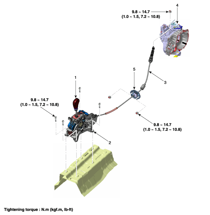
| 1. Shift lever knob & boots 2. Shift lever assembly 3. Shift cable |
4. Manual control lever 5. Shift cable retainer |
| Components |
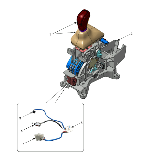
| 1. Shift lever & boots assembly 2. Shift lever assembly 3. P position switch |
4. Shift lock solenoid 5. Manual mode switch housing 6. Main connector |
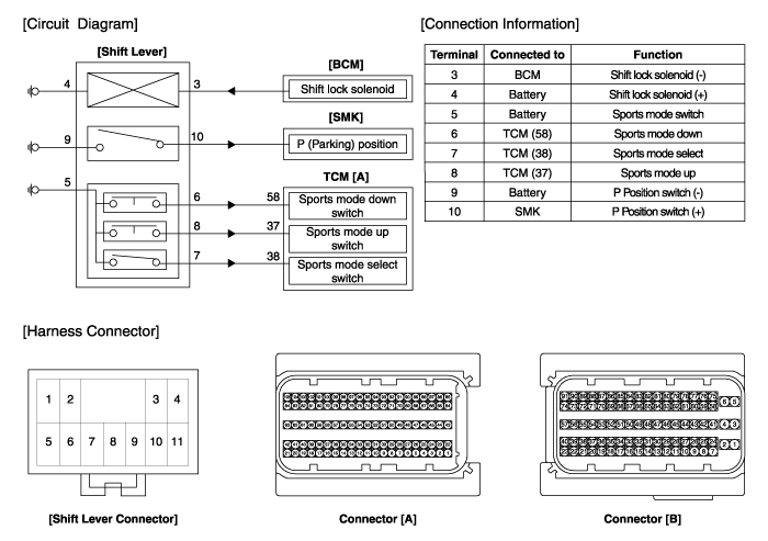
Schematic diagrams
| Schematic Diagrams |
Repair procedures
| Removal |
| [RHD] |
| 1. |
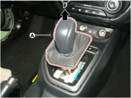
Disconnect a boots from the console upper cover.
|
| 2. |
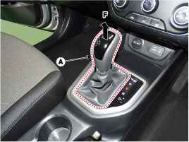
Pull the knob (A) in the direction of "F" and remove the knob.
|
| 3. |
Remove the floor console assembly.
(Refer to Body - "Floor Console")
|
| 4. |
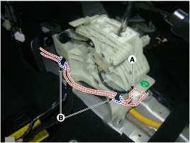
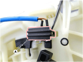
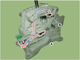
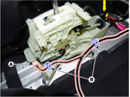
Disconnect the connector (A) from the shift lever.
|
| 5. |
Disconnect the wiring mounting clips (B).
|
| 6. |
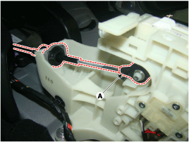
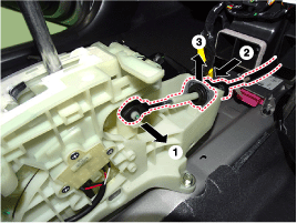
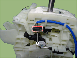
Disconnect the control cable.
|
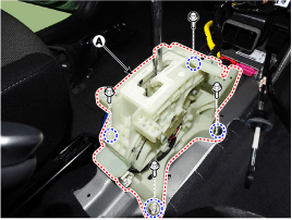
| 7. |
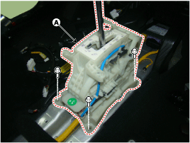
Remove the bolts and then shift lever assembly (A).
|
| 8. |
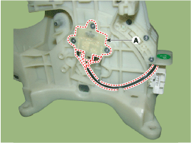
Remove the P position switch mounting bracket (A).
|
| 9. |
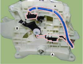
Disconnect the P position switch (B) and shift lock solenoid (A).
|
| 10. |
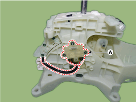
Disconnect the manual mode switch housing (A).
|
| 11. |
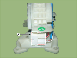
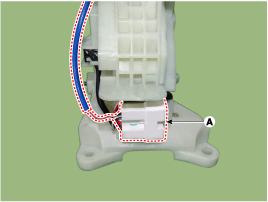
Disconnect the main connector (A) from the shift lever.
|
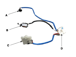
| 12. |
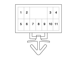
P position switch, shift lock solenoid, manual mode switch housing,
main connector assembly (A).
|
| 13. |
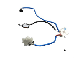
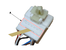
Remove the mounting bracket (A) of terminals from the main connector.
|
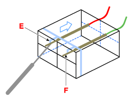
| 14. |
Remove each terminals (F) of the P position switch (A), shift lock solenoid
(B), manual mode switch housing (C) after released lock (E) from the
main connector (D).
|
| [LHD] |
| 15. |
Disconnect a boots from the console upper cover.
|
| 16. |
Pull the knob (A) in the direction of "F" and remove the knob.
|
| 17. |
Remove the floor console assembly.
(Refer to Body - "Floor Console")
|
| 18. |
Disconnect the connector (A) from the shift lever.
|
| 19. |
Disconnect the wiring mounting clips (B).
|
| 20. |
Disconnect the control cable.
|
| 21. |
Remove the bolts and then shift lever assembly (A).
|
| 22. |
Remove the P position switch mounting bracket (A).
|
| 23. |
Disconnect the P position switch (B) and shift lock solenoid (A).
|
| 24. |
Disconnect the manual mode switch housing (A).
|
| 25. |
Disconnect the main connector (A) from the shift lever.
|
| 26. |
P position switch, shift lock solenoid, manual mode switch housing,
main connector assembly (A).
|
| 27. |
Remove the mounting bracket (A) of terminals from the main connector.
|
| 28. |
Remove each terminals (F) of the P position switch (A), shift lock solenoid
(B), manual mode switch housing (C) after released lock (E) from the
main connector (D).
|
| Installation |
| 1. |
To install, reverse the removal procedure.
|
 Inhibitor Switch
Description and operation
Description
•
The inhibitor switch mounted on the upper of transaxle and connected
with shifter lever.
•
...
 Shift Cable
Components and components location
Components
1. Shift lever knob & boots
2. Shift lever assembly
3. Shift cable
4. Manual control lever
5. shift cabl ...
Other information:
Hyundai Creta GS 2014-2026 Service Manual: Repair procedures
Inspection
Front Door Lock Module Inspection
1.
Remove the front door trim.
(Refer to Body - "Front Door Trim")
2.
Remove the front door module.
(Refer to Body - "Front Door Module")
...
Hyundai Creta GS 2014-2026 Service Manual: Air Cleaner
Components and components location
Components
1. Air duct
2. Air cleaner lower cover
3. Air cleaner element
4. Air cleaner upper cover
5. Air intake hose
Repair procedures
Removal and Installation
1.
Remov ...
© 2017-2026 www.hcrmangs.com


