Hyundai Creta: Automatic Transaxle Control System / Input Speed Sensor
Hyundai Creta GS 2014-2019 Service Manual / Automatic Transaxle System / Automatic Transaxle Control System / Input Speed Sensor
Description and operation
| Description |
| • |
Input speed sensor uses an electric current type hall sensor in which
the current is changed by the magnetic variation.
|
| • |
Input speed sensor (A) and output speed sensor are integrated and installed
in the transaxle.
|
Functions
| • |
Measures the rate of rotation of the input shaft inside the transaxle
and delivers the readings to the TCM.
|
| • |
The sensor provides critical input data that's used in feedback control,
torque converter clutch control, gear setting control, line pressure
control, clutch activation pressure control, and sensor fault analysis.
|
Specifications
| Specifications |
â–· Type: Hall Effect Sensor
|
Operation condition [°C(°F)] |
(-40 ~ 150) -40 ~ 302 |
|
|
Output voltage (V) |
High |
1.18 ~ 1.68 |
|
Low |
0.59 ~ 0.84 |
|
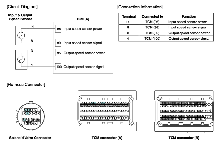
Schematic diagrams
| Circuit Diagram |
Repair procedures
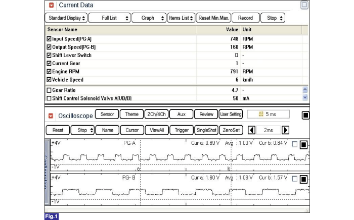
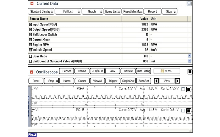
| Inspection |
| 1. |
Using the GDS, check the input / output speed sensor waveforms.
Fig 1) Input / Output speed sensor at low speed
Fig 2) Input / Output speed sensor at high speed
|
| Removal |
| 1. |
Remove the valve body assembly.
(Refer to Valve body System - "Valve Body")
|
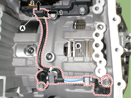
| 2. |
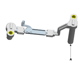
Disconnect the input & output speed sensor connector (A) from the main
wiring.
|
| 3. |
Remove the input & output speed sensor (B) after removing the bolts
(2ea).
|
| Installation |
| 1. |
To install, reverse the removal procedure.
|
| 2. |
Check fluid level after filling the automatic transaxle with fluid.
(Refer to Hydraulic System - "Fluid")
|
 Transaxle Oil Temperature Sensor
Description and operation
Description
•
Transaxle oil temperature sensor monitors the automatic transaxle fluid's
temperature and conveys the readings to T ...
 Output Speed Sensor
Description and operation
Description
•
Output speed sensor uses an electric current type hall sensor in which
the current is changed by the magnetic variation ...
Other information:
Hyundai Creta GS 2014-2019 Service Manual: Rear Door Belt Inside Weatherstrip: Repair procedures
Replacement
1.
Remove the rear door trim.
(Refer to Rear Door - "Rear Door Trim")
2.
Remove the rear door belt inside weatherstrip (A).
3.
To install, reverse the removal procedure.
...
Hyundai Creta GS 2014-2019 Service Manual: Repair procedures
Adjustment
Transaxle Control Module
(TCM) Learning
When shift shock is occurred or parts related with the transaxle are replaced,
TCM learning should be performed.
In the following case, TCM learning is required.
•
Transaxle assembly ...
© 2017-2026 www.hcrmangs.com
