Hyundai Creta: Electric Power Steering / Steering Column and Shaft
Components and components location
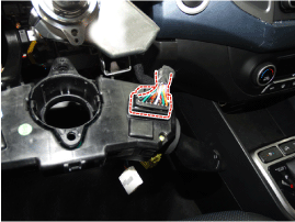
| Components |
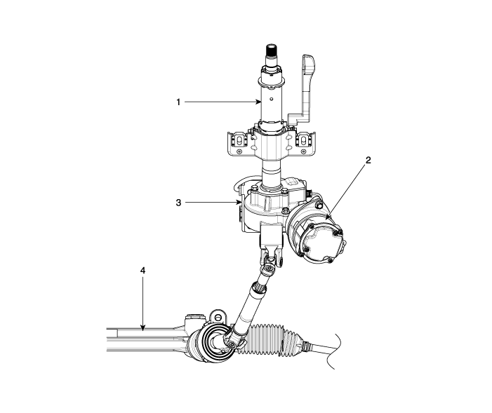
| 1. Steering
column 2. Motor |
3. ECU 4. Steering gear box |
Repair procedures
| Removal |
|

| 1. |
Disconnect the battery negative cable from the battery and then wait
for at least 30 seconds.
|
| 2. |
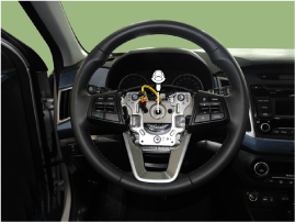
Turn the steering wheel so that the front wheels can face straight ahead
|
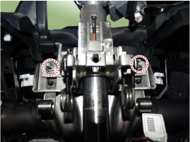
| 3. |
Loosen the torx bolts which are located on the both side of the steering
wheel.
|
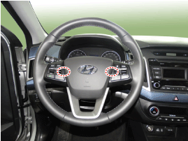
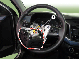
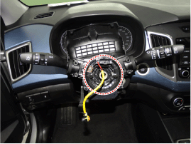
| 4. |
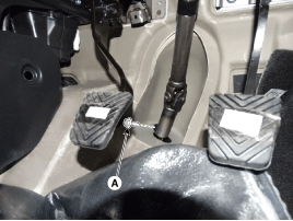
Remove the DAB module then disconnect the clock spring connector (A).
|
| 5. |
Loosen the steering wheel lock bolt and then separate the steering wheel.
|
| 6. |
Remove the steering column shroud after loosening screws.
|
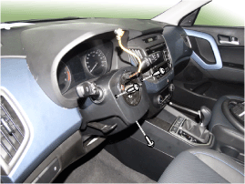
| 7. |
Remove the clock spring and then disconnect the connector.
|
| 8. |
Remove the multifunction switch.
|
| 9. |
Disconnect the multifunction switch connector.
|
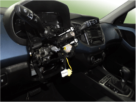
| 10. |
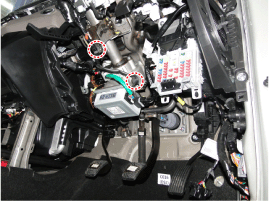
Remove the crash pad lower cover.
(Refer to Body - "Crash Pad")
|
| 11. |
Remove the wiring clip.
|
| 12. |
Disconnect the connector (A) & (B).
|
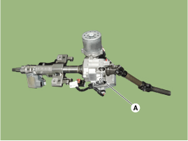
| 13. |
Loosen the universal joint bolt (A) and then disconnect the universal
joint assembly.
|
| 14. |
Loosen the mounting nut & bolt and then remove the steering column.
|
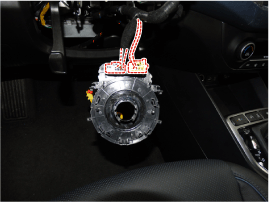
| Disassembly |
| Key lock assembly |
| 1. |
Make a groove on the head of special bolts (A) by a punch.
|
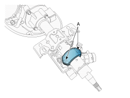
| 2. |
Loosen the special bolt using a screw driver and then remove the key
lock assembly from the steering column assembly.
|
| 3. |
Reassembly is the reverse of the disassembly.
|
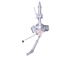
| Universal joint assembly |
| 4. |
Loosen the bolt (A) and then disconnect the universal joint assembly
from the steering column assembly.
|
| Inspection |
| 1. |
Check the steering column for damage and deformation.
|
| 2. |
Check the steering column for damage and deformation.
|
| 3. |
Check the join bearing for damage and wear.
|
| 4. |
Check the tilt bracket for damage and cracks.
|
| 5. |
Check the key lock assembly for proper operation and replace it if necessary.
|
| Installation |
| 1. |
Install in the reverse order of removal.
|
| 2. |
Perform the ASP Calibration.
|
| 3. |
Perform the EPS Type Recognition Procedure.
|
 Repair procedures
General Inspection
After or before servicing the EPS system, perform the troubleshooting and test
procedure as follows. Compare the system condition with normal condition in
the ...
 Steering Gear box
Components and components location
Components
[LHD]
1. Tie
rod end
2. Tie rod
3. Bellows
4. Dust
cap
5. Steering geer box
...
Other information:
Hyundai Creta GS 2014-2019 Service Manual: Cylinder Block: Repair procedures
Disassembly
ŌĆó
Use fender covers to avoid damaging painted surfaces.
ŌĆó
To avoid damaging the cylinder head, wait until the engine coolan ...
Hyundai Creta GS 2014-2019 Owners Manual: Cruise Control Operation
1. CRUISE indicator
2. SET indicator
The Cruise Control system allows
you to drive at speeds above 40
km/h (25 mph) without depressing
the accelerator pedal.
WARNING
Take the following precautions:
If the Cruise Control is left on,
(CRUISE indicator light in the
instrument clu ...
